

Western Electric Products - Payphones and Phone Booths - 233G Payphone (3-slot) Payphone Restoration Project
233G Payphone (3-slot) Payphone Restoration Project
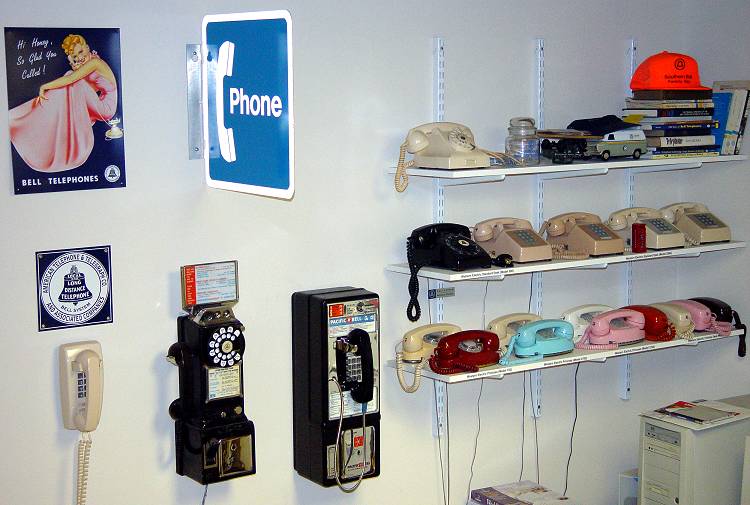
Sewing Machine - Automatic Answering Service “Mirrophone” wire ribbon recorder/player Telephones - PicturePhone - Bell Chime
The Beginning . . .
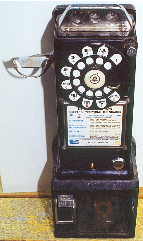
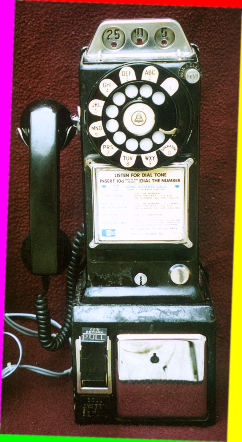
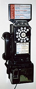
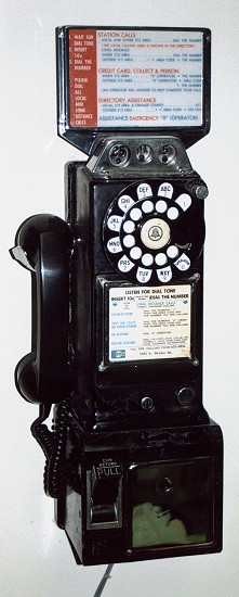
The above picture is what the 3-slot payphone looked like before restoration began.
David Massey’s project.

We Offer Personalized One-On-One Service! Call Us Today at (651) 787-DIAL (3425)

I acquired a Western Electric 233G payphone that was fairly complete from Bob Bartlett (Bob’s Antique Payphones). It is my first experience with a payphone and my first major telephone refurbishing project so I thought I’d share my restoration experiences on my web site. Among those that helped me acquire parts, schematics, and other assistance with this restoration project are Stan Schreier, Bobby Koch, Vern Potter, and others. This list of names will surely grow as I get deeper into this restoration.
This page contains a lot of graphics and may take a while to download. NOTE: Some images are hyperlinked to the full-size scans These full-size scans can be viewed by clicking on the images on this page.
For information on building a controller circuit to make your phone operate like a real coin-operated payphone, see Doug Alderdice’s website at http://mysite.verizon.net/dalderdi/phones/payphone.htm.
For a hand-drawn wiring diagram of hooking up a 233G, click HERE.
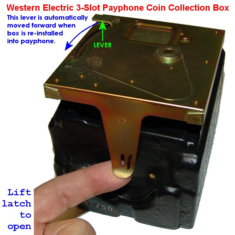
The Coin Collection Box
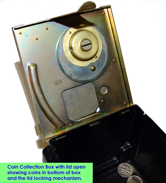
For instructions on opening the coin collection box and resetting the latch mechanism, see the following photos:
-
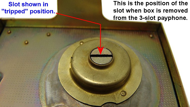
“Tripped mechanism (as it is when you remove the box from the phone)
-
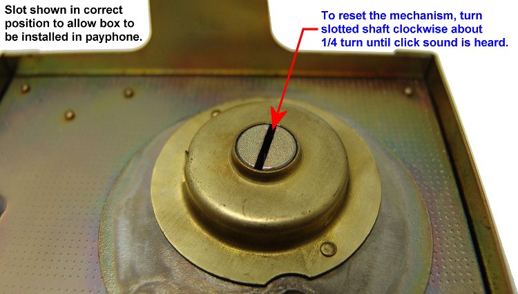
Reset the mechanism before placing back in payphone by turning slotted shaft of mechanism clockwise just over 1/4 turn until it “clicks” in place.
Let’s start off this “documentary” on my payphone restoration project by first looking at some photos of various sections and parts of the phone as I received it in the middle of August, 2000. The phone had no handset, coin box, or vault door. A bakelite terminal strip was broken inside at the top along with the coin return lever. The white plastic “hat” that covers and protects the coin relay was missing. The chrome parts had a film of dirt and probably nicotine from cigarette smoke that probably dated back to the days when the Beatles were introducing Rock and Roll to America. Yes, this phone represents an era when transistors were taking the place of vacuum tubes in consumer electronics, Touch-Tone® dialing was getting ready to be released to the public by Bell Labs through Western Electric and the Bell System, Arpanet was just around the corner (the predecessor to today’s Internet) and I wasn’t quite a teenager yet.
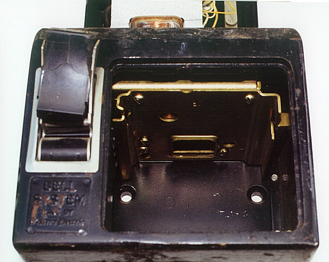 Photo #1: The broken pull bucket and the missing coin box and vault door. I have
obtained a coin box as of the end of August 2000 but still need to find
a vault door. The coin-return pull-bucket is still in disrepair -
not sure what I’m going to do to fix it - I may just find a replacement
for it.
Photo #1: The broken pull bucket and the missing coin box and vault door. I have
obtained a coin box as of the end of August 2000 but still need to find
a vault door. The coin-return pull-bucket is still in disrepair -
not sure what I’m going to do to fix it - I may just find a replacement
for it.
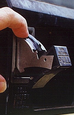
Photo #2: The broken pull bucket viewed from another angle.
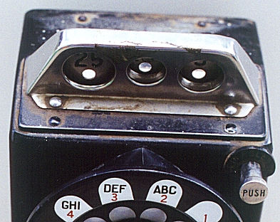
Photo #3: The dirt and corrosion on top where the coins are deposited. I was able to clean all the non-painted metal pieces pretty clean after taking these** pictures.
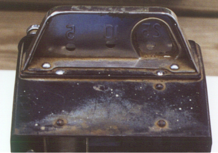
Photo #4: Back view of where coins are deposited and rear side of the top of phone.
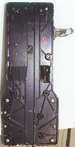
Photo #5: The back of the telephone.
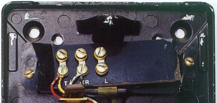
Photo #6: The broken terminal strip. A replacement was sent to me soon after this picture was taken.
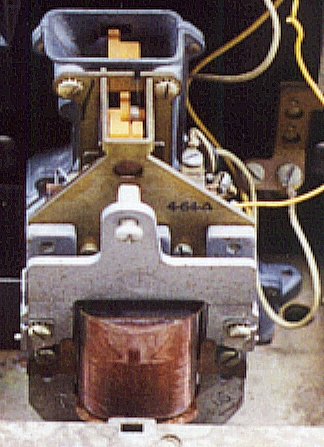
Photo #7: The coin relay - view 1. Normally there is a plastic “hat” over the top of this assembly to keep stray coins from shorting things out in the contacts of the relay or mechanically jamming it. A replacement hat was donated to me soon after this picture was taken.
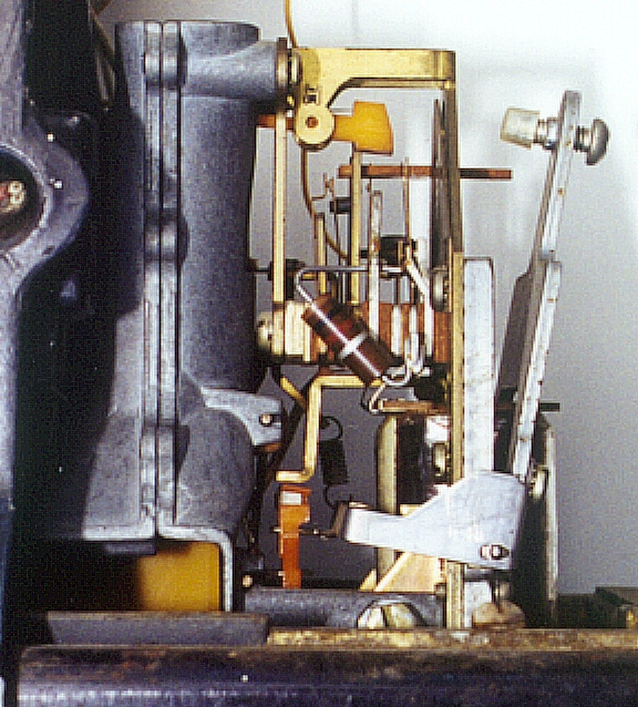
Photo #8: The coin relay - view 2 (left side as you face front of phone).
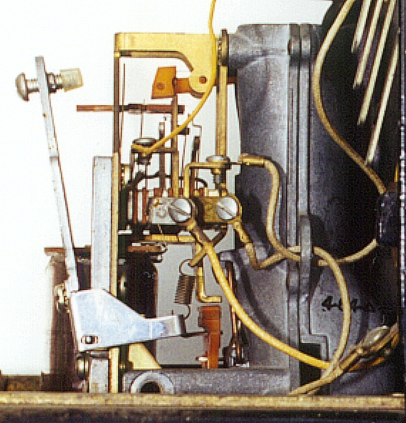
Photo #9: The coin relay - view 3
(right side as you face front of phone).
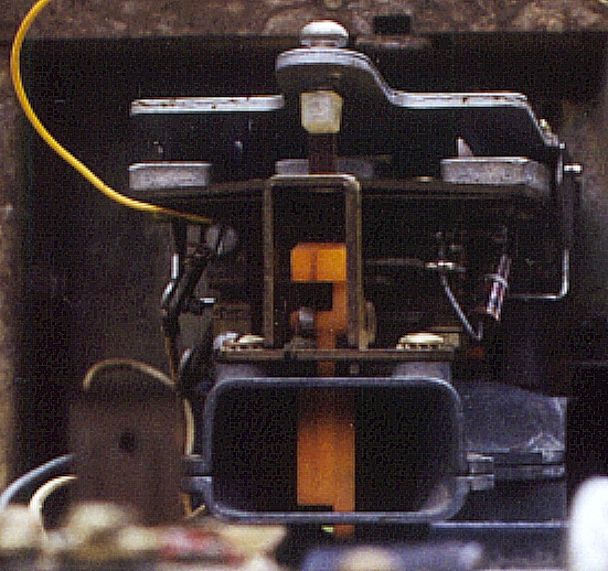
Photo #10: The coin relay - view 4
(looking down from above relay, front of phone would be toward top of this picture)
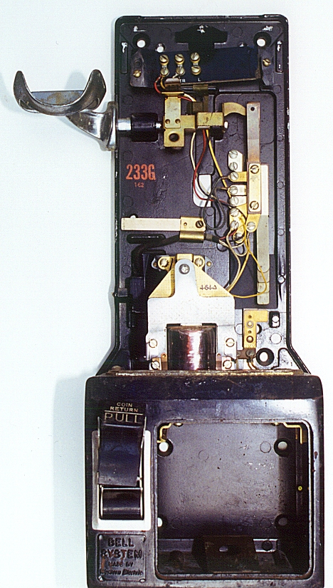
Photo #11: The back plate which contains the switch-hook assembly. Also shown is the coin relay assembly, the pull bucket, and opening for the coin box and vault door.
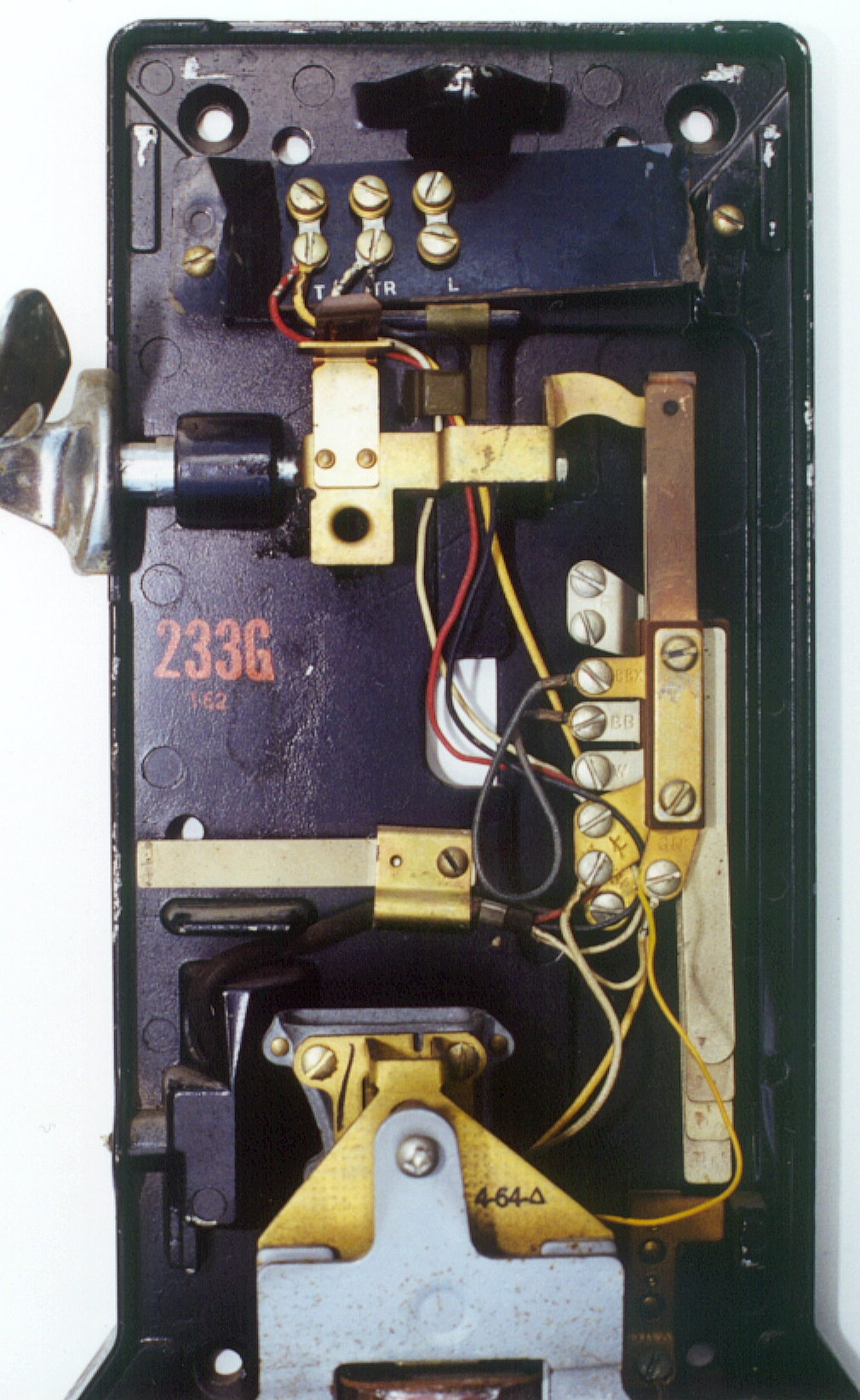
Photo #12: Close-up showing broken terminal strip at top, the switch-hook assembly, old handset cord entrance (about 2/3 down the picture) and top part of coin relay.
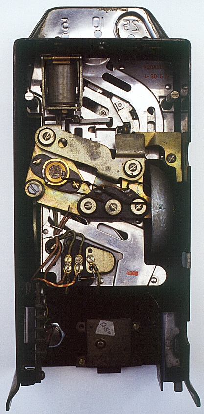
Photo #13: Close-up showing inside view of “top” housing. Note electromagnet in upper left corner. Also seen here is the solid gong on the extreme right side about half way down (edge of bell showing). More details on this later on.
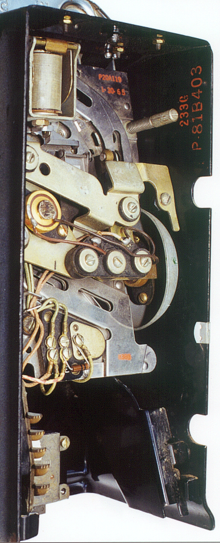
Photo #14: Same section of phone as in photo #13 above but viewed from an angle to show underneath view of bell (half-way down on the right side of housing) and other mechanical parts from a different viewing angle.
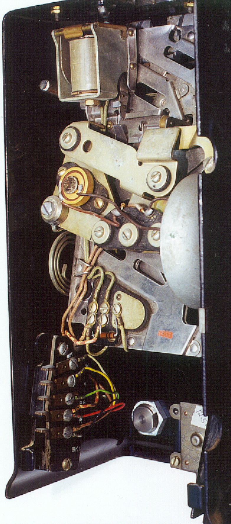
Photo #15: Same section of phone as in photo #13 above but viewed from an angle to show spiral metal “spring” called the cathedral gong (half-way down on the left side of housing) which makes a “bong” sound when quarters are deposited in the phone. Also in this view you can see the “nickel” electromagnet and the interconnecting contacts (lower left part of picture) which makes all electrical connections between the upper and lower housing assemblies when phone is assembled.
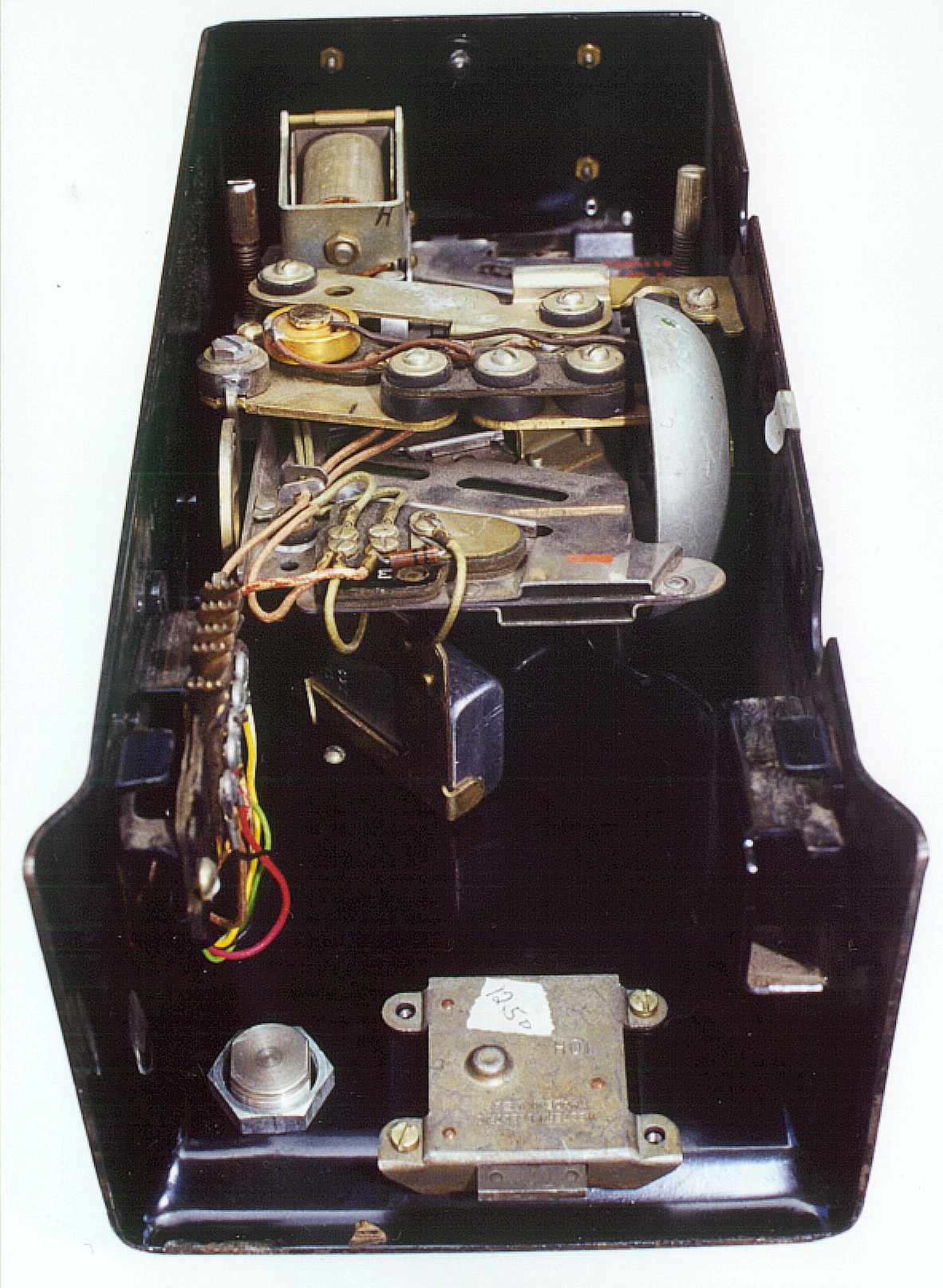
Photo #16: Same section of phone as in photo #13 above but viewed from an angle to show lock (bottom center of housing) and a metal can capacitor underneath the sub-chassis and mounted at an angle (just below the middle of picture and above the 10G lock).
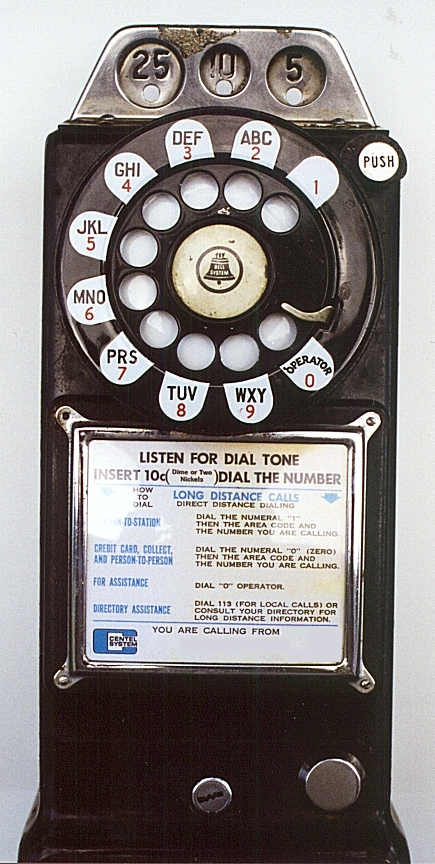
Photo #17: This is the front view of the upper housing.
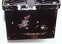
Photo #18: Bottom of lower housing showing paint condition.
October 2000 - The missing handset
I didn’t have any luck locating an exact replacement for the missing handset. I did the next best thing and modified the cord on an old hard-wired handset from a Western Electric 500 set. The original cord on the payphone was cut right where it exited the side of the phone. This gave me the information I needed to know how to modify the 500 handset cord to work with the payphone. Below is a picture comparing what was left of the original cord and the soon-to-be modified 500 cord:
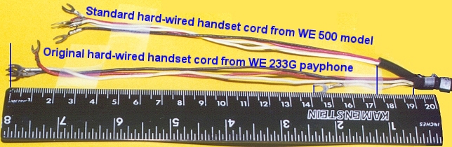
Notice that three out of the four wires in the original cord extend about 19cm from where the outer jacket was stripped. The fourth wire (one of the white ones) only extended about 5cm. The outer jacket on the standard 500 set cord extended about 2cm beyond the original payphone cord (the length between the 17cm mark and 19cm mark). This had to be stripped back as part of my modification. All four wires on the standard 500 set cord were the same length which meant than the excess length of one of the white wires just had to be looped and tucked out of the way in the payphone. The metal strain reliefs (far right in the picture above) were in about the same position in both cords. I used cellophane adhesive tape (Scotch tape) to hold the wires against the yellow paper for the photo thinking they wouldn’t show - but, as you can see, they do!
The Missing Vault Door and Coin Collection Box
I now have a coin box and a chrome vault door thanks to a couple of members of the ATCA club. Here is a photo of my phone with the addition of the handset and vault door. Click on image for full-size view.
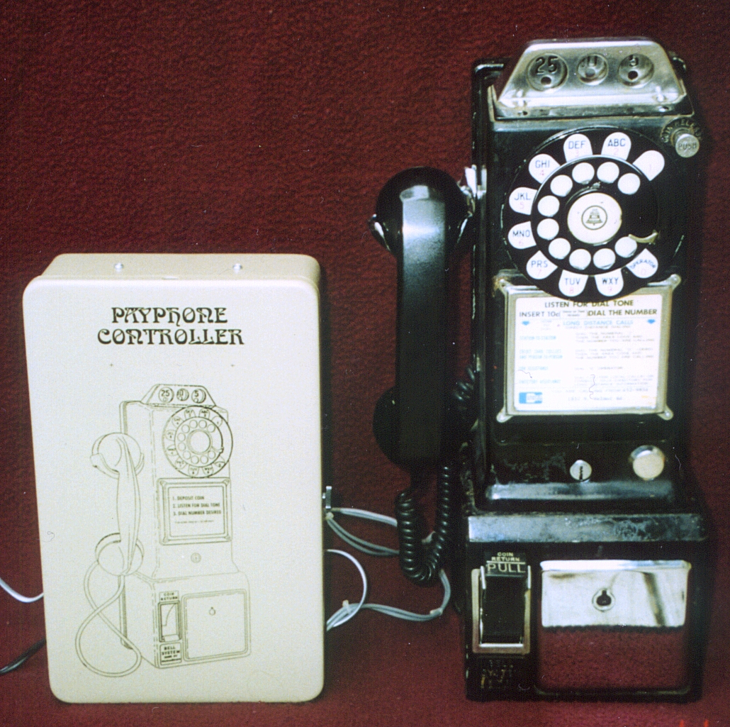
Here is a photo of the phone with the coin relay controller box (as before, click on this image to view full-size):
Here is a photo of the inside of the controller box:
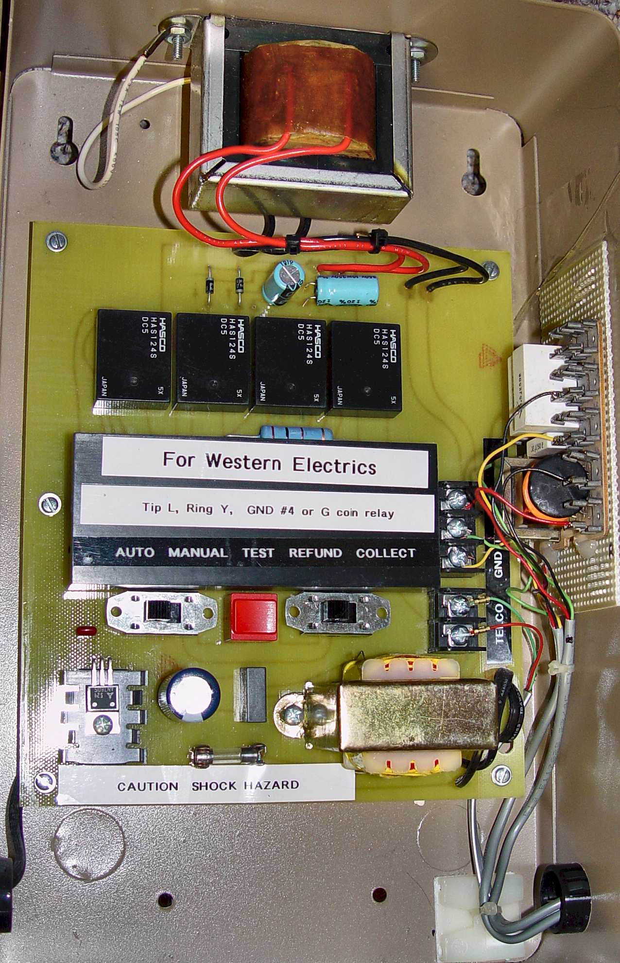
Click on image above to view full-size
This controller box was the last one available from a club member. I do not have schematics of this unit but there is another club member that has a website with a schematic of his design with parts list and description.
May 2001
I finally finished my telephone display in my basement and got the payphone its own spot on the wall. You can view the above image in two larger sizes than what you see above. Click HERE for a medium size image or HERE for large size. The vault door is really a bright and shiny chrome finish but the photo makes it look almost black.
That’s it for now on my payphone restoration. I hope to repair that broken coin-return pull-bucket someday.
If you are considering painting your 233G, here is a tip from one of the club members (June 16, 2003):
“I repainted my 233 this weekend and just taped over the [coin return] sticker. The sticker looks fine and the paint job turned out great. I’m really happy with the Rustoleum Satin Black. It’s a perfect match for the WE black. I taped over the “233G” [ink lettering] on the back-plate and when I removed the tape, I couldn’t see a difference in color or gloss.” - Jim Burnham


Reliable, secure high-speed internet
With CenturyLink Simply Unlimited Internet, you can choose from a wide range of available speeds that fit your online needs. Plus, you can connect several devices with super-fast in-home WiFi.
Order Now