


Western Electric- Telephones

Western Electric telephones made prior to the breakup of the Bell System (January 1, 1984) were designed and built to last for decades. If a Western Electric phone ever quit working your local Bell Operating company would send out the “telephone man” to your house and fix it for free. Those days of quality built telephones and free visits to your home by a telephone repair person are gone - replaced by cheap throw-away phones from Taiwan and China.
This web page is your starting point for technical information, photos, FAQ’s, posters, charts, etc. on Western Electric telephones.

Bell Phone Center employee tossing returned Western Electric phones that will end up at the Western Electric Recycling Depot to be either refurbished or scrapped.

We Offer Personalized One-On-One Service!
Call Us Today at (651) 787-DIAL (3425)

TABLE OF CONTENTS:
[The Telephone Book](#The Telephone Book) - Western Electric sales/marketing info on the Design Line telephones as well as the standard phones available around 1980.
[Bell Ringing Problems](#Does your Western Electric 500 telephone not ring) - Some things to try if your Western Electric phone does not ring.
PARTS AND REPAIRS - a Bell System Memorial public service “Yellow Pages” listing of collectors and dealers of antique telephones and parts for old phones.
Common Western Electric telephone models:
-
Model 500 Telephone - These were the “standard” rotary dial desk sets; probably the most common phone that was around in the later decades of the Bell System.
-
Model 554 Telephone - This was the wall mounted version of the 500 set. It had the same rotary dial, ringer, handset and network as the 500 set.
-
Models 1500 and 2500 Telephones - Touch-tone replacement for the 500 set.
-
Models 1554 and 2554 Telephones - Touch-tone replacement for the 554 set. This model design is still used in many retail stores such as Target, Home Depot, Sears.
-
TRIMLINE - The first Western Electric phone with the dial built into the handset. This is still a very popular style today.
-
PRINCESS TELEPHONE - “Modern” Western Electric phone.
-
DESIGN LINE TELEPHONES - Remember the “doughnut” telephone or the Mickey Mouse phone or the Country Junction phone or the numerous other special residential phones made by Western Electric in the 1970’s and early 1980’s?
-
[PANEL TELEPHONE](#Panel Telephone (model 750)) - Model 750
-
[CARD DIALER TELEPHONE](#CARD DIALER TELEPHONE)
-
OLDER PHONES THAN THOSE SHOWN ABOVE like the model 302.
-
BUSINESS MODELS (LIKE KEY SYSTEM) The following three documents were contributed by Larry Bayern:
-
Multibutton pamplet - “How to use” pamphlet
-
Multibutton - Another “How to use” pamphlet
NOTE: An excellent website by Paul Fassbender lists the various models of Western Electric phones along with the Bell System Practices index for these models. Click HERE for his home page.
Also, Jeremy Walters sent us a color copy of “The Bell System’s Line of New Products and Services” brochure which you can view by clicking HERE.
-
PAYPHONES - Western Electric payphones.
-
PICTUREPHONE - A Bell Labs development that never caught on due to high cost and other factors.
-
COLOR CHARTS - Official color charts from Western Electric showing the available colors of Western Electric telephones and accessories in the years prior to the 1984 divestiture. Includes color code numbers.
-
POSTERS - Four posters published by the Bell System and by AT&T post divestiture. A great reference with photos and brief descriptions of most telephones made by Western Electric and the historical first telephones designed by Alexander Graham Bell.
-
FAQ’s*- Frequently Asked Questions.
-
How to use your new Bell Telephone - An interesting old Bell System pamphlet sent to me by Chuck Vasquez.
-
[TEST SET PHONE (A.K.A., “BUTTSET”)](#Test Set Phone)
-
[OTHER TECHNICAL INFORMATION](#OTHER TECHNICAL INFORMATION) - Miscellaneous scans from the Bell System Practices manuals. Photos of telephone parts. Subsections on ringers, networks, handsets, dials, etc.
-
[LAMP \ INFORMATION](#LAMP INFORMATION)
-
[THE ZONES!](#THE ZONES!)
-
[Dial Telephone Switching Equipment](#Dial Telephone Switching Equipment)**
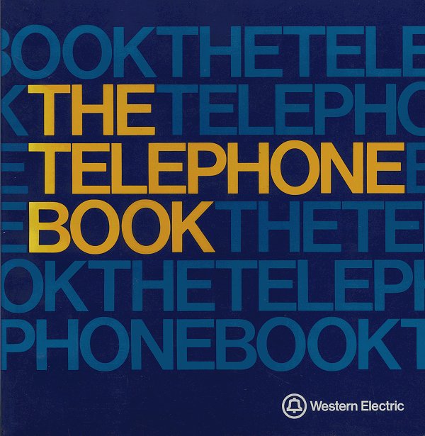
For general information on the Western Electric phones that were in use in the 1970’s and early 1980’s, please click HERE or on the image above for scans of Western Electric sales literature of various models. NOTE TO DIAL-UP MODEM USERS: This is a LARGE file so plan on waiting a long time to download it.
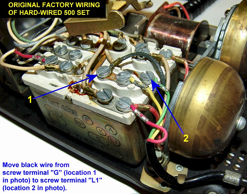
Does your Western Electric 500 telephone not ring
but you can still dial a call and both sides of a conversation are audible? Then try moving the ringer’s black wire to the network terminal marked “L1”. See schematic and photo for more info.
Does your Princess 702B phone not ring?
Does it have a
5-conductor line cord (yellow, black, white, red and green wires)? Try placing a
jumper wire from terminal “L1” to terminal “G” on the network box inside as
shown in this modified Bell System
drawing.
FAQS:
If you have a vintage Western Electric phone (or phones) that you would like to use on today’s phone lines, read on. If your phone predates the 1950’s you may find some information on your model HERE. General FAQ’s about wiring vintage telephones to work on today’s analog telephone lines follow this paragraph and then you will find links to specific models for more detailed information including photos and schematics.
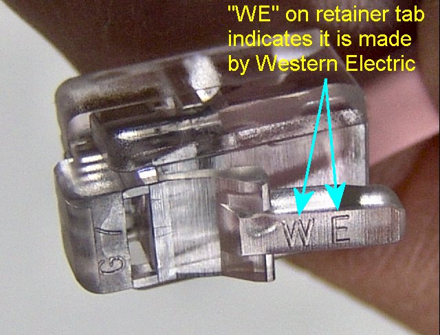
Q. How can I tell if the modular handset cord or line cord on my telephone is genuine Western Electric or has been replaced by a cheap generic brand?
A. You should see the letters “WE” molded on the little plastic retainer tab of the modular plug as seen in this photo.
Q. What were the model numbers and names of the later models of Western Electric telephones?
A. Refer to the following sketches (click on a sketch and you will go to that model’s web page):


Q. My model of Western Electric phone is older than those shown above. Do you have a web page on the older models?
A. I have information on some of the older models HERE.
Q. How about the newer phones like the “doughnut” phone that Western Electric made but are not shown above?
A. I have information on the so-called “Design Line” phones HERE. Also, check out the end of this web page for some other types of Western Electric phones.
Q. My phone gets a dial tone but doesn’t ring. What can I check first to make sure the bell is not broken?
A. There are a few common reasons for this (beyond a broken ringer or internal network).
-
Back in the days when the Bell System charged customers extra for “extension phones” (defined as any phone other than the one primary phone they gave you as part of the monthly service cost) people would disconnect the bell’s coil from the internal network terminals. This would make the phone “invisible” to the Bell Telephone Company technician running “impedance” checks on a phone line. Each working bell of each phone in a customer’s house would add a load which was easily detected by test equipment. So the first thing to check is the wires coming from the coil on the bell (ringer) assembly to see if they are hooked up to anything inside the phone. Some coils have only two wire leads (newer phones) and other coils have four wire leads. If you find loose wires from your bell’s coil then there is a good chance they were disconnected by a previous owner of the phone to avoid detection of the phone by the local phone company.
-
Another wiring issue that can cause the bell not to ring is the possibility that the phone was wired for “party-line” service which would prevent the phone from ringing on today’s “private-line” (single-party) service. The yellow wire in the old line cords are no longer used for party identification.
-
There is a possibility that the loudness control on the phone was modified internally to allow the ringer to be silenced. See Western ** **Electric Ringers web page for more info.
-
And last but not least, the “bias spring” on the ringer ** **assembly may be set to the low sensitivity setting which would prevent it from ringing or ringing reliably if you already have a bunch of phones in your house. The bias spring setting is easily changed in most phones and in most cases all you need is a finger to make the adjustment once you have the phone apart.
Q. My touch-tone phone gets dial tone and rings but I can’t dial out. I don’t hear any tones when any of the buttons are pressed - just a weak clicking sound. What could cause this?
A. Some of the vintage Western Electric touch-tone phones were polarity sensitive meaning that if the wires going to the telephone jack contacts were reversed the dial would not make tones. It’s a simple fix - just reverse the red and green wires in the telephone jack in the wall and the phone dial should then work. Later model Western Electric phones had “polarity guard” circuits installed which allowed the phones to be wired in either direction.
Q. How much is my phone worth?
A. We don’t do appraisals or even try to give “ball park” figures. If you want an appraisal or estimate of worth, please contact the following organization:
Appraisal of Historical Items
To inquire about the value of your personal Bell (AT&T, Western Electric), or other historical items or equipment, please use the following link to WhatsItWorthToYou.com. WhatsItWorthToYou.com is independent of The Porticus Centre and have trained specialist in various categories that will help in determining the true value of your item(s). At Porticus, we do not know the value of items, we simply are a historical database of documentation.
**Q.**What happened to Western Electric?
A. The named changed several times after the breakup of the Bell System. One of the names which still exists is Lucent Technologies. Lucent then sold it’s entire consumer telephones operations to VTech, Inc., who has set them up in a new division called “Advanced American Telephones”. This division will make all the consumer phone equipment under the AT&T name. The Enterprise Equipment, (Merlin, Definity, Spirit, Dimension, and other business related communications equipment was spun-off by Lucent and became Avaya, Inc. The structured cabling business of Western Electric, which was part of Lucent, was also spun-off the same year, 2000 and was part of Avaya. This business was more commonly known as AT&T Network Systems or Systimax PDS (Premises Distribution Systems). SYSTIMAX was sold to CommScope, Inc. in 2004, however, the Systimax business still manufactures cabling, phone and data jacks, and computer Ethernet cords here in the U.S.A. at the former Western Electric plants. The distance between the great days of Western Electric and what’s left of it now have become greater, and even more diluted. It’s interesting to note that Lucent was acquired by Alcatel of France in 2006. The name of the combined company is Alcatel-Lucent.
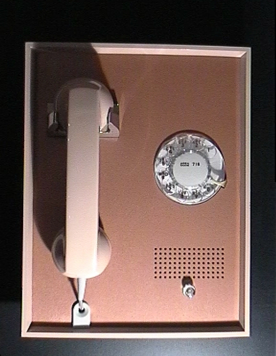
Panel Telephone (model 750)
The Western Electric panel phone mounted into a wall. A lucky visitor to this web site has a model 750B in NOS (New Old Stock) condition made in 1969! His name is Stefan Schmaus and he lives in Germany. Here are links to some photos of his phone:
CARD DIALER TELEPHONE

NOTE: Due to the huge PDF file size, this document is not on the web server.
A big thanks to Russ Pate who sent copies of the pages from the manual to scan.
Automatic Card Dialer Telephone - A rotary dial version can be seen in this 21-second video clip from the 1962 Seattle World’s Fair Bell System movie called “Calling Century 21”. Using punched plastic cards, customers can “speed dial” their calls. Large file; 4.4 Megabytes!
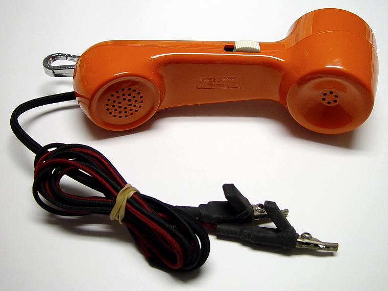
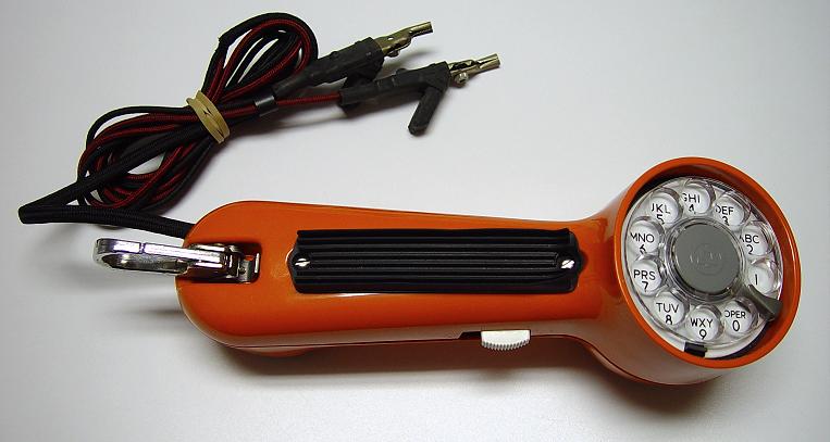
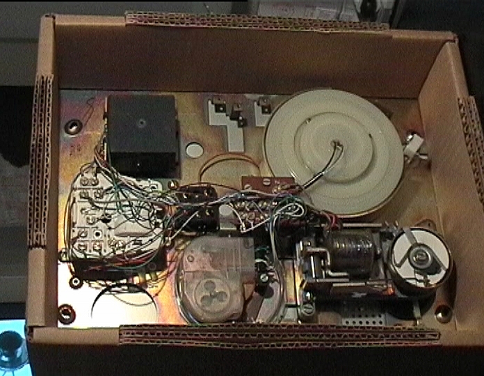
Test Set Phone**(A.K.A., the “butt-set”, as in** “butting into a conversation” which is one use for this item)
Lineman’s Test Set
** **
**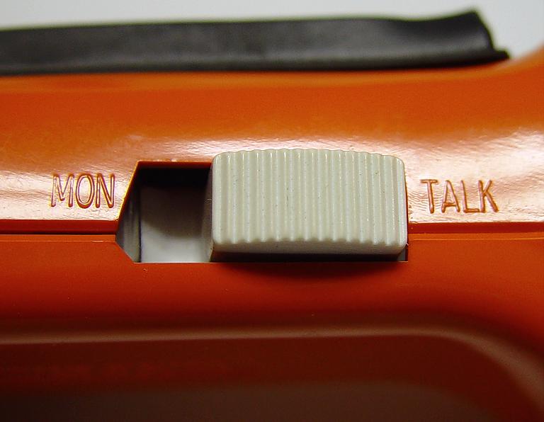
Monitor/Talk
Switch
Test Clip
For making temporary “clip-on” connections
 Genuine Bell
of course!
Rotary Dial Belt Hanger
“The term “butt-in” and “butt-out” came from telephone terminology. The reason for the name Butt-set, is that this device is named after the inventor Mr. Buttinsky. I have seen cut sheets from Graybar for Harris -Dracon TS-21 sets that refer to them as Buttinsky’s. The telephone industry was one of the largest employers, so it is not surprising that many phone-related terms became common usage.” - James Stettler
This is not a phone like you would have in your home unless you are a phone collector like me! It was used by the “Telephone Repairman” to troubleshoot problems in phone line circuits or to monitor, break in (or “butt in”) to a telephone conversation already in progress.
The following information was contributed by Dennis D Hock and Steph Kerman:
“The official Bell System model number of a test set like this is 1013 if equipped with permanent clip leads for an installer/repairman or 1014 if equipped with an interchangeable test cord plug for CO/PBX use. The earlier 1011 variations were distinguished by letter suffixes as was the later 1015 test set with pushbutton dial. However no difference in 1013/1014 code regardless of whether it was blue, yellow or orange. (Obviously they were already beginning to “lose it” when they did this.)” - Steph Kerman
“The circuit is a very basic type which utilizes a capacitor, resistor, inductor, T1 transmitter and a LA1 i think receiver. The Monitor switch is used to create a circuit similar to that in the 302AA, 500E/F sets, that is a high impedance bridge to monitor. It is not high enough that it won’t attenuate data service however. This is formed by using the capacitor in series with the receiver the switch and the line. In talk mode the inductor in series withthe transmitter and bridged by the receiver and the capacitor.” - Dennis
“Actually, the iron core device is a bridging transformer with hi-Z (10K?) primary winding to permit monitoring on data circuits at a much higher impedance than would be possible without a transformer. The transformer is as best as I recall used as an inductor during talking to keep DC out of the REC so that the REC can be protected with a varistor for click suppression…. a refinement not found on the 1011 which used a simple series circuit.
There is a BSP in the 100, 103 or 106 BSP divisions describing various cord configurations. and showing a schematic.
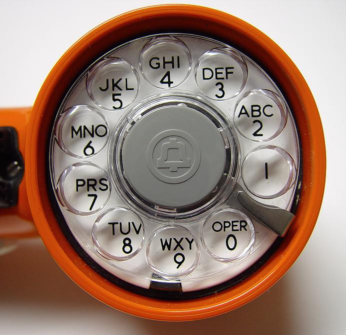
BTW the dial is a standard #10A Trimline dial except equipped with a porcelain number plate.” - Steph Kerman
( [Return to beginning](#Test Set Phone) of this article)
Bell System Practices
Station Service Manual
Volume 1 (Nov. 1982)
Please Note: These documents are posted for non-commercial use by hobbyists, collectors, etc. For commercial use, please order BSP reprints from LUCENT TECHNOLOGIES shown at top of this page.
If you have a need for any other material from the Station Service Manual as shown in the table of contents BELOW but not yet available from this web site, please contact us and we will send a scan to you via return e-mail. The images are very large to allow good resolution and you will probably need to scroll up/down and left/right to see the entire images.
TABLE OF CONTENTS:
NOTE: Since this page is updated as specific requests are received from website visitors, only those items with hyperlinks below are available at this time. If you see something in this list that has no hyperlink(s) and you need a copy of the item, please write us. The latest scans I have done are available as GIF format or PDF format. Most sections that have been scanned have been removed from this table of contents and placed with the specific web page for that model (like the 500 series).
GENERAL AND ASSOCIATED APPARATUS
- Auxiliary Signals - Identification, Installation, Operation, Maintenance, and Connections
- Inductive Noise
- Station Ringing Apparatus - Selection and Limitations
- Radio Signal Suppression for Telephone Sets
- Packaging and Handling - Disconnected Station Apparatus
- Buzzers and Bells - Identification, Installation, Maintenance, Limitations, and Connections
- Station Transformers
- MIA Handset
- G6-, G7-, G8-, G13-, G66-, and K6-Type Handsets (Amplifier)
- G36-Type Handset
- 238, 276, and 277 Types Amplifiers
- 151-, 241-, and 242-Type Amplifiers
- 315-Type Amplifiers
- Telephone Sets and Associated Station Apparatus - Selection of Indoor Locations
- Modular Type - General information
- 581A Telephone Set Bases (wiring page 1) (wiring page 2)
FUNCTIONAL SETS AND ADJUNCTS
- 1200AR1 and 1200AT1 TOUCH-A-MATIC 12 Automatic Dialer
- 5001T01A TOUCH-A-MATIC Telephone Set, S Series
- 5011T01A TOUCH-A-MATIC Telephone Set, S Series
OTHER TECHNICAL INFORMATION
- Handsets - Identifying various Western Electric handsets
- Networks found in Western Electric phones
- Ringers (electromechanical bells) in Western Electric phones
- Dials - Touch Tone or Rotary
- Wiring Product Standards - Official AT&T/Western Electric part numbers for various connectors and wiring tools.
- Western Electric Phone assembly drawings with main part numbers:
- Standard Desk Phones
- Standard Wall Phones
- Trimline Desk Phone
- Trimline Wall Phone
- Trimline Components
- Telephone Set Components
- Princess Phone
- Modern Candlestick drawings:
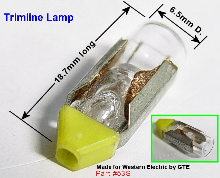
LAMP INFORMATION
The following information, supplied to me by Steve Schlink, concerns some of the various bulb types used in Western Electric phones (for Princess phone bulb information, see the Princess Phone page.)
|Lamp #|Voltage|Base|Life|EFC|COMMENTS| |51|7.5|Min. bayonet|1,000|| |51A|10|ANSI #6|15,000|460|1A2 Lamp| |51B|6|ANSI #6|20,000|1580|| |52|14.4|min. screw|1,000|| |52A|24|ANSI #6|8,000|430|| |53|14.4|min. bayonet|1,000|| |53A|10|ANSI #6|15,000|460|| |53B|6|ANSI #6|5,000|1580||
Steve’s notes follow:
-
ANSI #s refer to the wedge at the very tip of the lamp, not the overall dimensions.
-
EFC - End Foot Candles
-
The only difference between a 51B & 53B is that the 51B is .11 inches longer - the electrical specs are identical, and both are 240 ma. while the 53A is only 40 ma. @ 10V.
-
Another lamp is the 53S which is believed to be used in the older Trimline phones (non-LED versions).
THE ZONES!
HERE is an interesting (if not somewhat entertaining) chart showing the “zones” from a central office location where certain models of phones were designed to work best. It was published by the Bell System and donated to this website by Paul Wills. If you would like to download the PDF format of this document for printing, click HERE.
Miscellaneous:
The Number Card Archive If you need a copy of an original rotary dial phone number card or want to know more about this topic, you’ve got to visit the Number Card Archive!
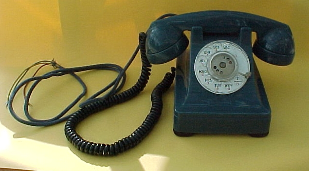
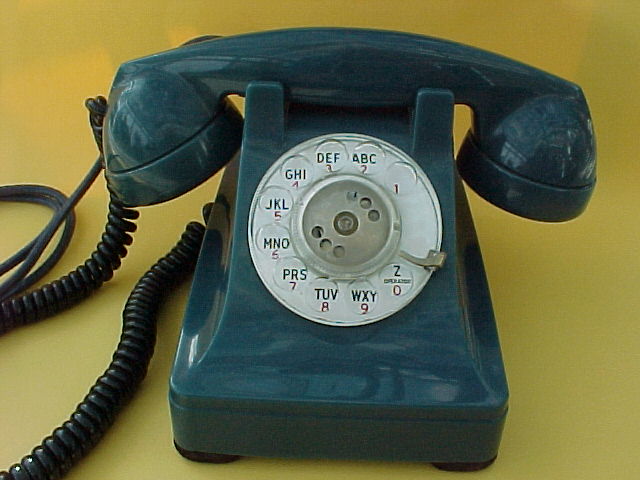
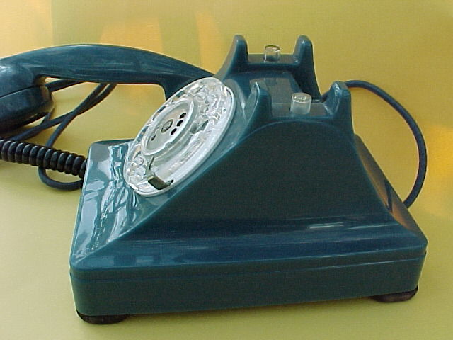
Rare colors of Western Electric phones in like-new condition command large sums of money on ebay. A recent example of this occurred on May 26, 2001 with a blue model 302. Here are the photos of that phone which sold for $3,949.99 on eBay (Item #1147731969).
“However, if you exclude the top two bidders' foolishness you get bidder #3 at $999.57. That’s about market value on this set. Don’t think that a blue WE302 is suddenly as valuable as a San Francisco potbelly. this was a combination of a fluke and a grudge match. who was it who said “a fool and his money are soon parted”?” - quote and paraphrased from Jonathan D. Finder, ATCA member.
| |
| |
|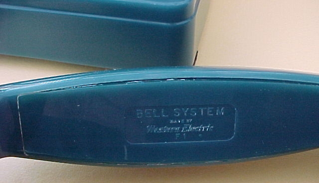 Handset markings|
|
Handset markings|
| |
| Carbon microphone element showing date cod of March 1949.|
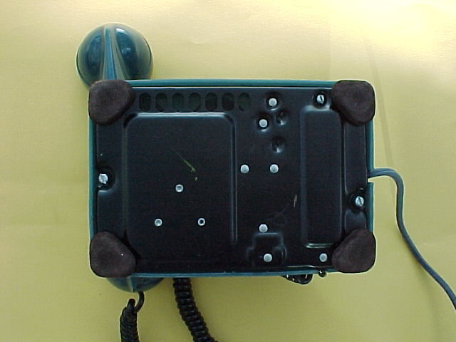 Bottom of phone|
From AT&T “Notes on Distance Dialing” 1975:
Section 5. 9. Audible tone signals
- Precise tones plan: +- 0.5 % frequency tolerance; +-3 dB amplitude
- Dial tone: 350 + 440Hz, -13 dBm per frequency
- High tone: 480Hz at -17 dBm
- Low tone: 480Hz + 620 Hz at -24 dBm per frequency
- Busy: low tone @ 60 IPM (50% tone on tone off)
- Reorder: low tone @ 120 IPM (50% tone on tone off)
- Audible Ringing: 440 + 480 Hz @ -19dBm per frequency
- Old tones have a level of 61 to 71 dBrnC.
- Old dial tone consists of 600 Hz modulated by 120 Hz when supplied by a tone alternator or 133Hz when supplied by an interrupter. … Other combinations were also used.
- Old high tone: 500 Hz (tone alternator) or 400 Hz (interrupter)
- Old Audible Ring typically consists of 420Hz moduled by 40Hz. Other combinations were also used.
thanks to Tony Roza for this info.
Dial Telephone Switching Equipment
As the telephone business grew, central offices grew in complexity. The switchboards were something to behold; many operators sitting in long rows inserting plugs into countless jacks. The cost of adding new subscribers increased in geometric proportions, causing one general manager to write that he could see the day that he would go broke merely by adding new subscribers.
There was a need for a break through of some kind. Almon Strowger went a long way towards providing it by developing the first dial system, called Step‑by‑Step. Other electromechanical systems that followed were: Panel and crossbar. Though these three systems differ considerably, they are all activated by electrical pulses from rotary‑dial telephones, which set into action a complex arrangement of relay‑controlled contacts. The advantages of automatic switching over manual switchboards include faster, more reliable service and reduced costs to subscribers.
Dial telephone equipment evolved to allow automatic dialing capability for telephone subscribers. Dial equipment is activated the moment the telephone handset is removed from its cradle on your phone instrument. An electrical connection is made to signal the automatic switching equipment in the exchange office to connect dial tone to your line.
The dial tone has the same meaning as the manual switchboards operator’s “Number, please.” It means the: switching equipment is ready to handle your call and you can now dial your number.
The first three digits of a local 7 digit telephone number determines the central office number; the last 4 digits identify a particular subscriber’s line in that office.
When a number is dialed, the switching equipment counts electrical pulses made by the dial wheel as it returns to its normal position. Each pulse represents a digit. For example, when the number 4 is dialed, 4 pulses are counted by the switching equipment as the dial wheel return to normal. A particular series of digits dialed identifies the telephone number of the desired subscriber.
When all digits of the called number are dialed, the connection is made to the called subscribers line.
Ringing current is sent out on the line causing the ringer to ring in the called subscribers telephone. Once the connection is made and the called subscriber answers, ringing current is removed and conversation can begin. The connection is released when either party hangs up.
Step by Step System
Step by Step is the oldest and simplest dialing system. It is a form of direct‑dial control, in that switches are directly responsive to dialed digits for each stage of the dialing process.
The heart of this system is a relay operated switch with a vertical rod with horizontal wipers affixed to it. As a digit is dialed, the rod with wipers moves up the banks of terminals the number of pulses of the digit dialed‑ The rod and wipers then rotates on the banks of terminals to an idle contact and connection to the next switch is made. Each succeeding digit dialed activities another switch, building a step‑by‑step connection through the central office. When all digits have been dialed, the connection is established and ringing current is applied to the line.
Step‑by‑Step was the predominant switching system for the first half of the century and remained the system of choice for small communities until the 1970’s.
Crossbar System
Crossbar equipment, like the Panel System, uses common control equipment to increase efficiency and speed of calling. The Crossbar switch consists of a horizontal bar, a vertical bar, and a contact spring that causes contacts on the switch to close and establish a connection through the central office.
All digits dialed are received and stored in an originating register units, senders, and various common control equipment activated to establish a connection from subscriber to called subscriber.
Crossbar Systems are extremely fast in making connections and can handle calls with more speed than other systems. Generally this type system was used for big city operations after 1938.
Panel Connector Frame
The panel system is partly a common control switching machine. It has the capability to store any digits dialed after the dial tone is received.
As digits are received by senders, switching equipment move: into action by causing brass rods with multiple brushes or wipers to move upward on banks of term’‑.pals to locate air available trunk to the office or number called. Other sender. operations then select the telephone number which was dialed and a connection through the office is completed. Ringing current is then applied to the called subscribers line and the ringing starts at the called subscriber’s telephone set.
After establishing the connection to the called subscribers, the senders and associated equipment are released to handle other calls.


Reliable, secure high-speed internet
With CenturyLink Simply Unlimited Internet, you can choose from a wide range of available speeds that fit your online needs. Plus, you can connect several devices with super-fast in-home WiFi.
Order Now