


Western Electric Products- Receivers & Transmitters
Sewing Machine - Automatic Answering Service “Mirrophone” wire ribbon recorder/player Telephones - PicturePhone - Bell Chime
This page will briefly describe the design evolution and technical operation of telephone handsets with emphasis on the two key elements of any handset - the transmitter (microphone) and the receiver (speaker).
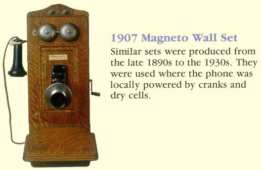
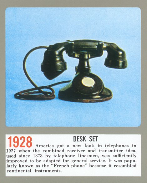
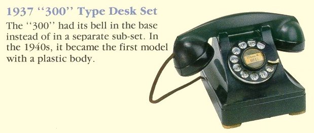
Prior to the days of one-piece handsets where the mouthpiece and earpiece (transmitter and receiver elements) were in one convenient housing, telephones had a separate housing for the receiver and the transmitter (see this photo of an old telephone with separate housings for the receiver and transmitter). Then in 1928 along came the so-called F-series handset that became the handset of the the Bell System for many decades. For some examples of telephone models that the F-series handset was used, see the 200 model, 300 model.
Later, the so-called “G” series handset became available and was found on the 500 set and later models. And in the spirit of Alexander Graham Bell’s dedication to the hearing impaired, Bell Labs developed a special “G” type handset for the hard of hearing called the “amplified handset”. For the Bell System Practices section on amplified handsets, click HERE. To view a Bell System advertisement on amplified handsets, click HERE.
In the seventies the “K” type handset was introduced. Instead of the nice round earpiece and mouthpiece of the earlier styles, a squared look was used - not as comfortable on your ears as the older round earpieces - unless you have square ears! To me the “K” handset marked the beginning of the cheap phones like we see today. Here is a photo of what this one looks like.
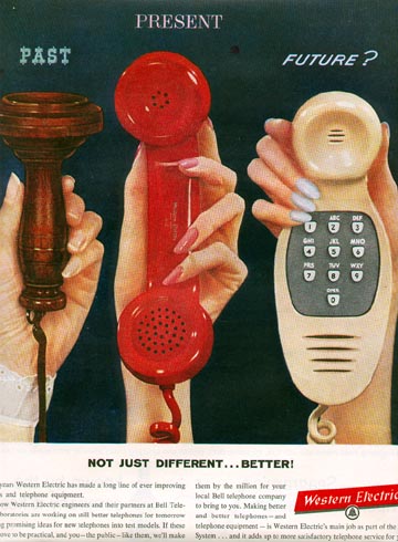
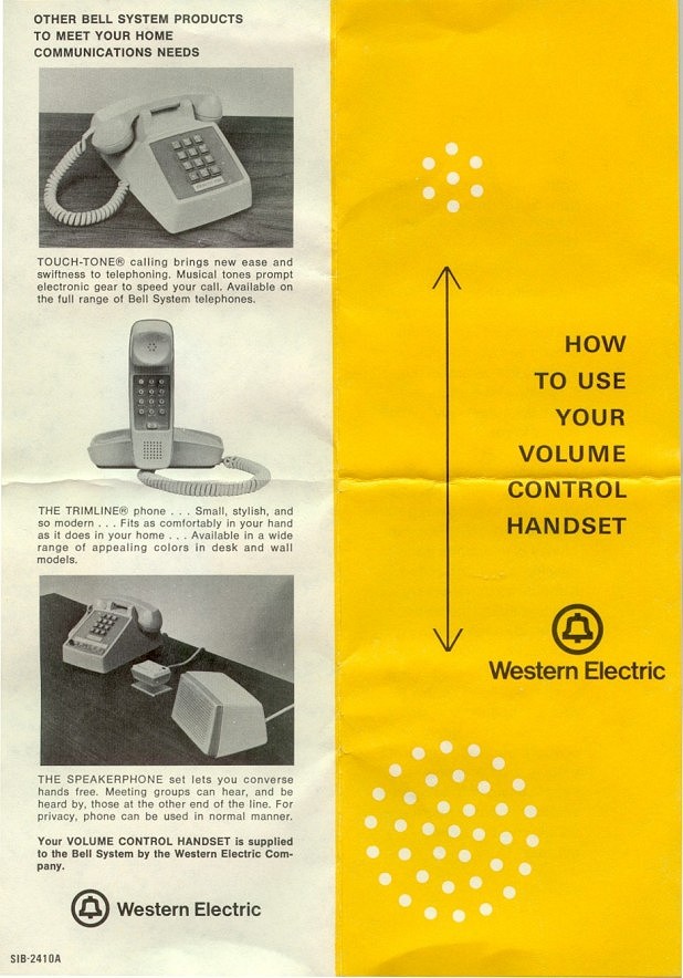
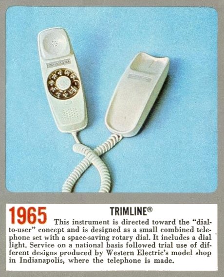
An old Bell System advertisement shows what might have been a future handset which was, in fact, prototyped but never mass-produced. It was known as the schmoo telephone but the final design was later known as the Trimline phone.

We Offer Personalized One-On-One Service!
Call Us Today at (651) 787-DIAL (3425)

The G Series Handset
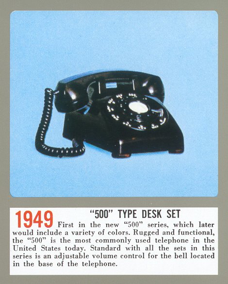
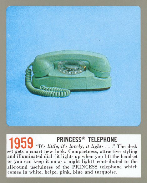
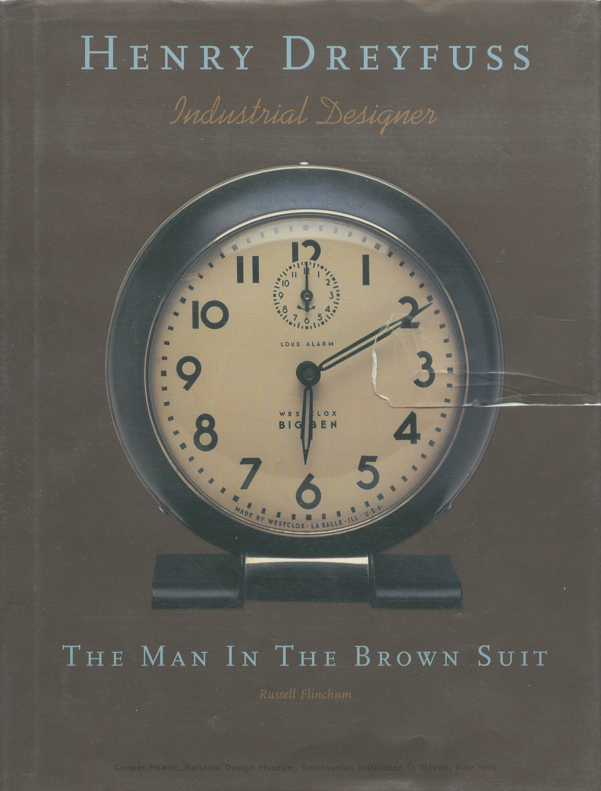
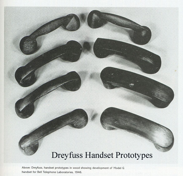
This is the most common style “modern era” handset found on Western Electric telephones in the USA. This handset was first introduced in the 1949 release of the model 500. Following the model 500, the G3 became the standard handset of the 554, 2554, 2500, 702 and 2702 (Princess) Western Electric models and is still the most common handset style found on payphones in the USA and possibly in other countries. It was designed by Henry Dreyfuss. A display of his model evolution can be seen by clicking HERE (courtesy of Paul A. Rauth).
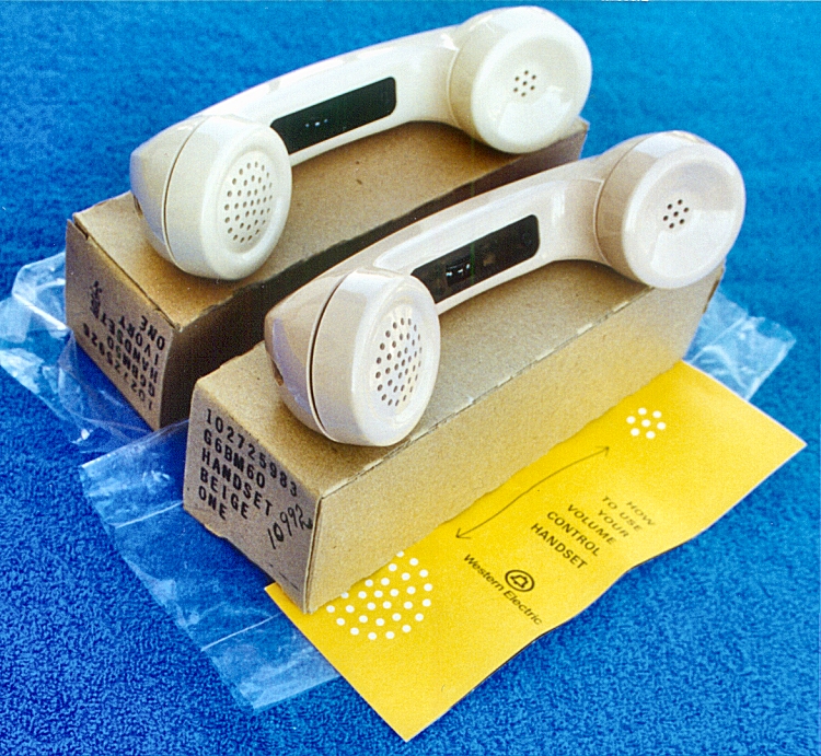
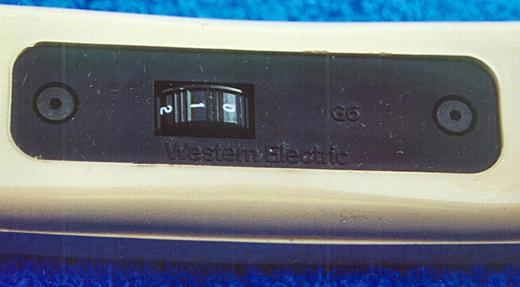
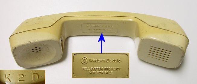
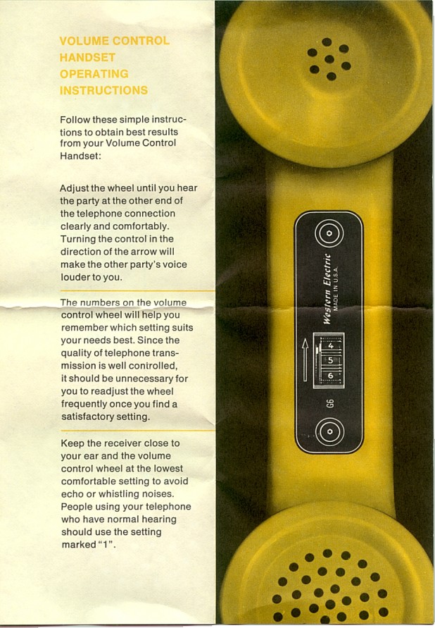
The Western Electric G6 model was like the G3 except it had a built-in amplifier with volume control. Click on photo 1 below to view two of these handsets - one in ivory color and the other in beige. The colors in the photos are lighter than what they really are in real life (the ivory on top looks almost white!). Photo 2 is a close-up photo of the volume control. Note the “Western Electric” brand name and the model “G6” embossed in the black plastic part of the handset. To view the instruction sheet that came with the handset, click HERE for one side of the instruction sheet and HERE for the other side of the instruction sheet.
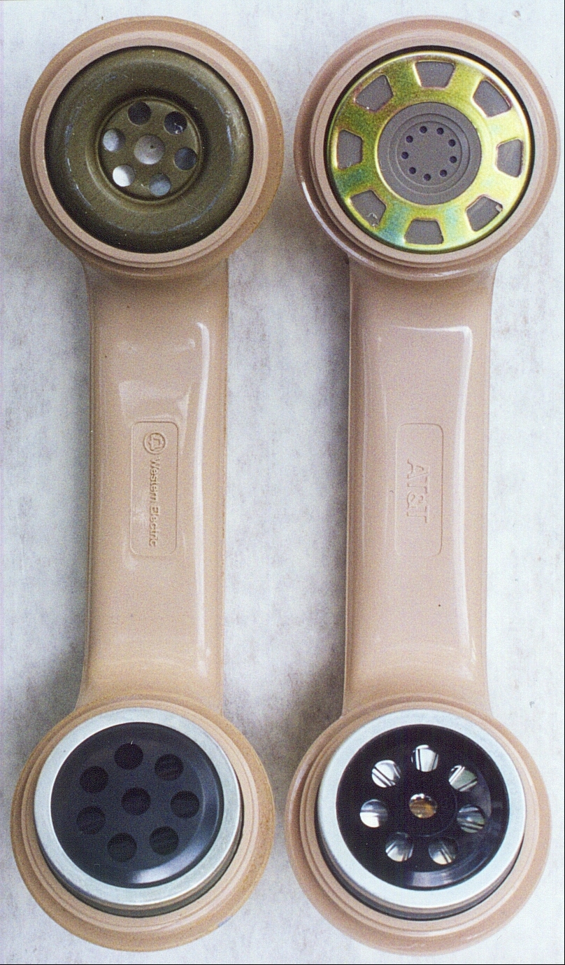
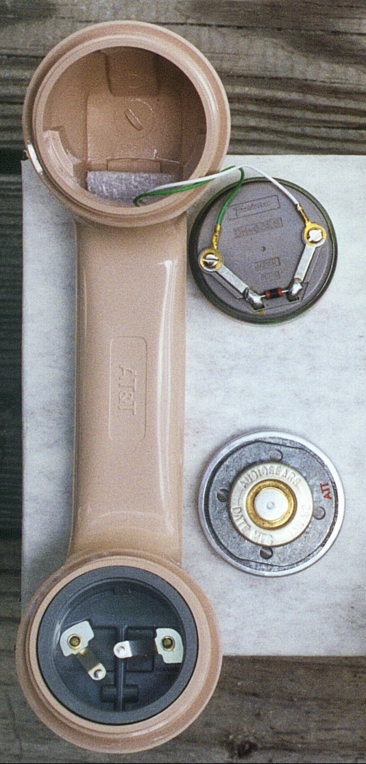
Below are some photos of the changes that took place in the internal components of the handset when Western Electric became ATT Technologies/Lucent after the breakup of the Bell System. Although not that obvious from the photos, the cheapness of the non-Western Electric components in the AT&T handset is quite obvious in real life. The plastic handset shell and screw-on caps seemed to be made in the USA and other than the molded logos (see below), they appeared identical.
Click on above image for full-size image
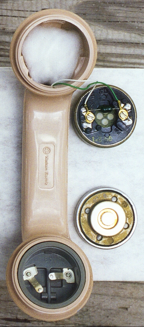
On the left is a view of the all-USA made components of a Western Electric handset (plastic screw-on caps removed to show transmitter and receiver elements).
On the right is the handset AT&T made in the early 1990’s using non-USA made components. Note the protective moisture barrier in the transmitter element (lower right corner of picture) is missing.
Click on above images for full-size image
On the left is a photo of the Western Electric transmitter and receiver elements removed from the handset and placed face-down to expose the back side of the elements.
On the right is a photo of the transmitter and receiver elements that AT&T used in the early 1990’s removed from the handset and placed face-down to expose the back side of the elements.
![]()
Enlargement of Western Electric logo molded in handset
![]()
Enlargement of AT&T logo molded in handset
The Receiver Element
In 1969 the Bell Labs announced a new receiver element, called the “LB” receiver, that is a thinner version of the one used in the Trimline telephone. It was to be used in the new “electronic” telephones of the future.
I dissected an old ITT brand receiver element found in an old ITT 500 set. You can view the photos I took by clicking on the links below:
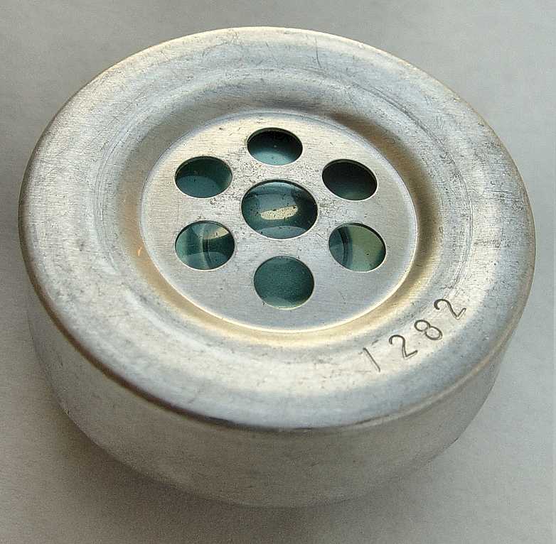
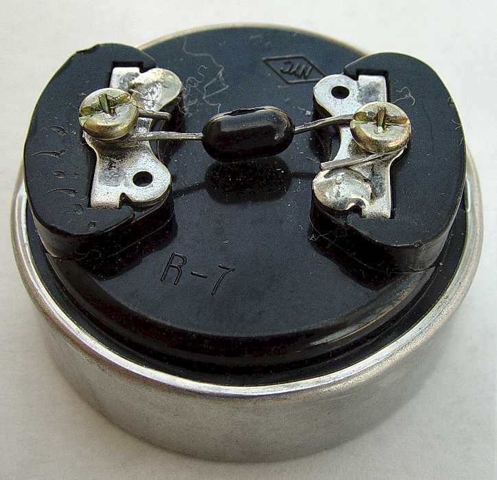
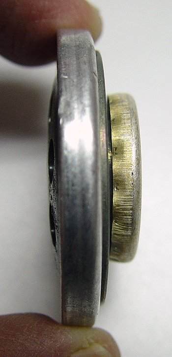
View of front of receiver before dissection - View of back of receiver before dissection (has terminal screws and varistor)
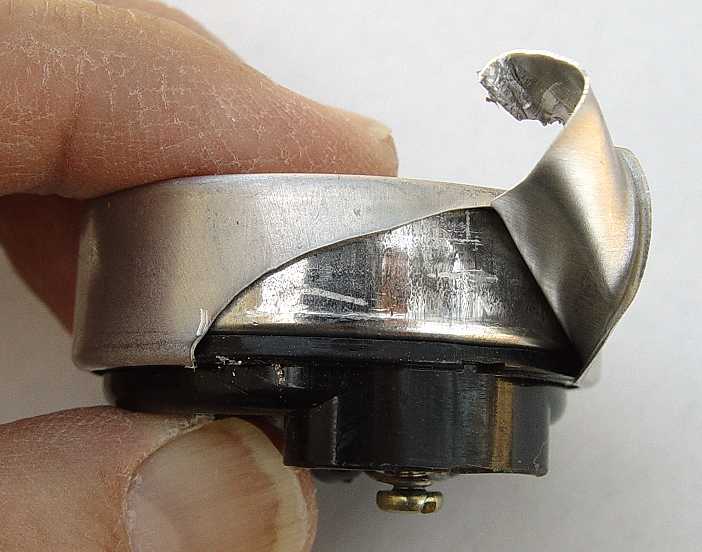
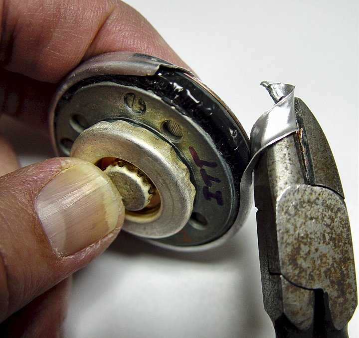
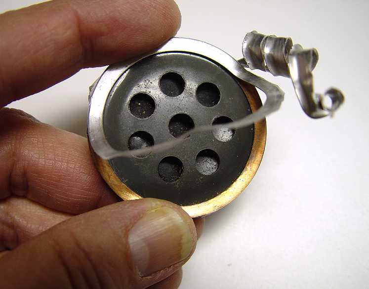
View of me peeling off the outside metal “shell” - View of receiver after removing outside metal “shell”
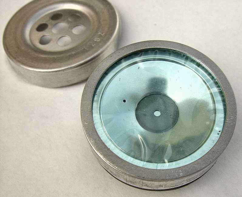
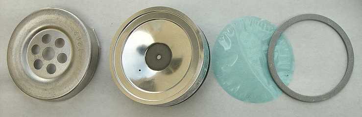
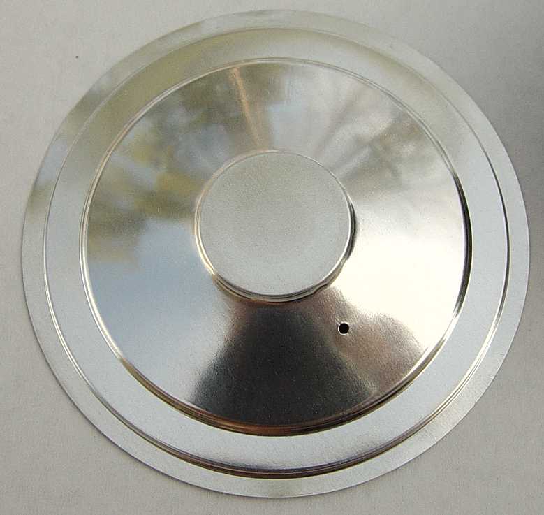
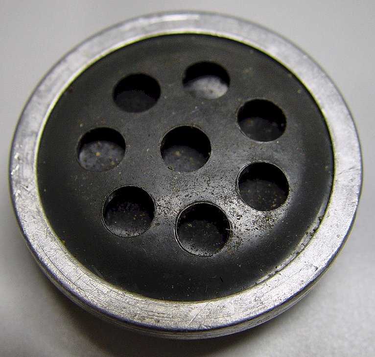
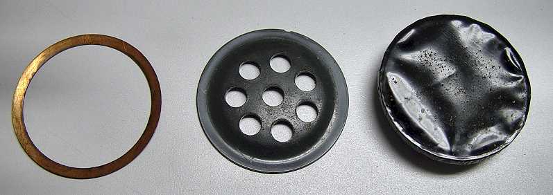
View of outside shell, aluminum diaphragm, plastic moisture barrier membrane and membrane gasket
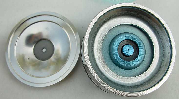
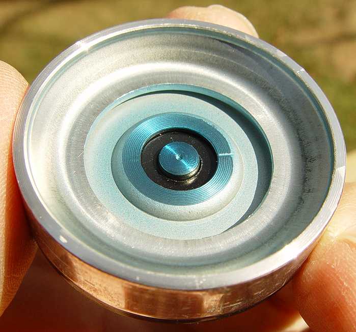
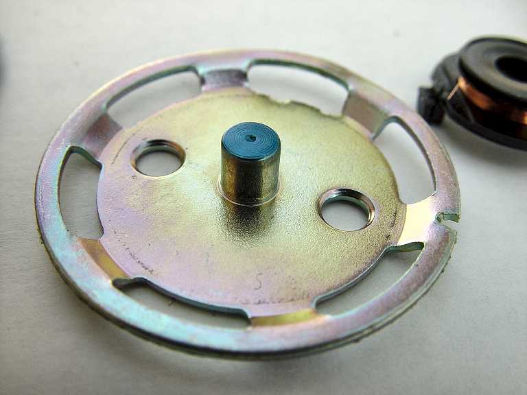
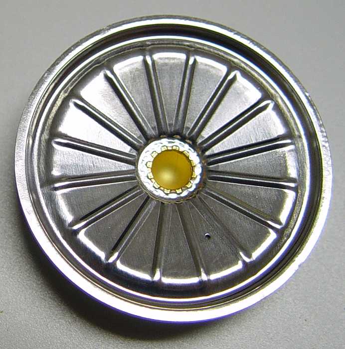
View of diaphragm removed exposing the electromagnet/magnet assembly underneath - (note the iron disk with small hole mounted in the center of the aluminum diaphragm)
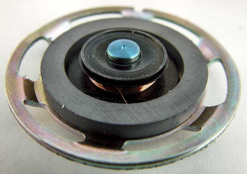
View of other side of diaphragm - Close-up of electromagnet/magnet assembly
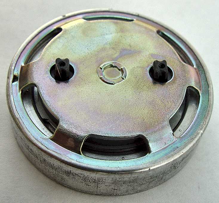
Back side of electromagnetic/magnet assembly - Inside view of electromagnetic/magnet assembly
View of iron core and steel frame after removing electromagnet (coil) and ceramic magnet
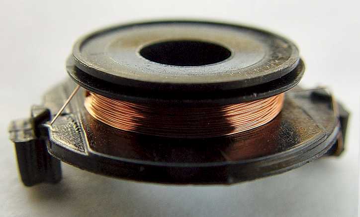
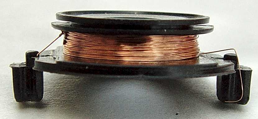
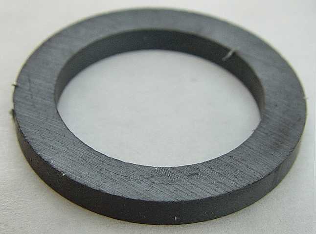
Close-up view of coil - another view \ of coil - Close-up view of ceramic magnet
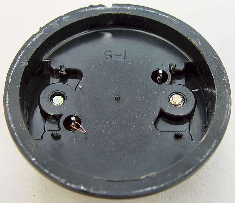
View of the inside of the rear plastic piece that has the terminal screws and varistor (note the broken wires that came from the coil still soldered to the terminal posts)
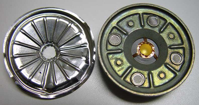
The Transmitter Element
The
transmitter is basically a variable
resistor whose resistance changes in synch with the sound waves that strike the
transmitter’s diaphram - a
thin aluminum conical disk protected from moisture and dust and other
contaminants by a thin plastic
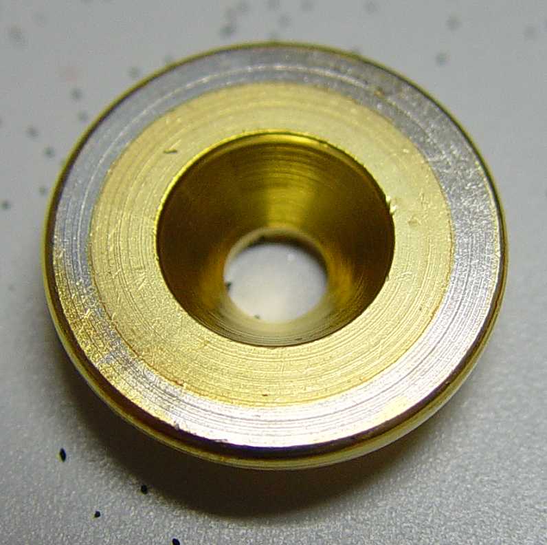
membrane. A gold-plated metal " cup"
forms one electrical connection and is filled with
carbon granules. The
second electrical connection is the gold-plated metal " button"
that is attached to the diaphram
and is suspended in the carbon granules.
I also dissected an old ITT brand transmitter element found in an old ITT 500 set. You can view the photos I took by clicking on the links below:
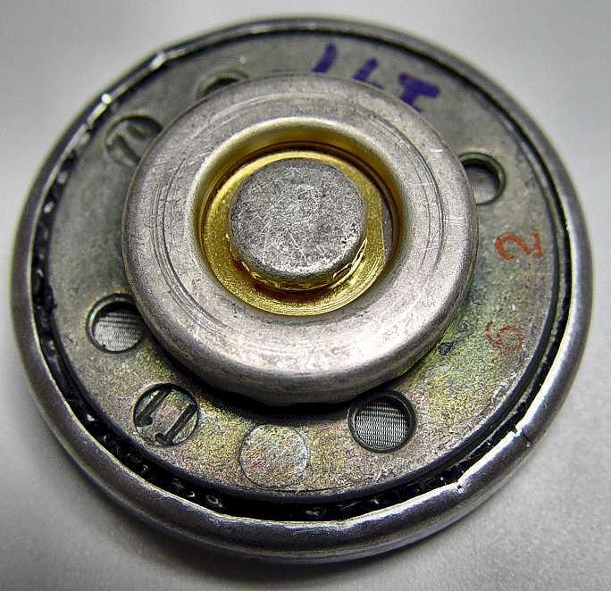
Front view before dissection - Rear view before dissection - Side view before dissection
Photo of me peeling the outer metal shell off the main structure - Ready to remove shell
Photo showing (from left to right) gasket, front cover, moisture barrier membrane
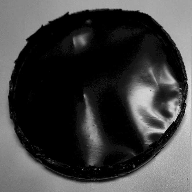
Close-up of aluminum diaphragm and moisture barrier
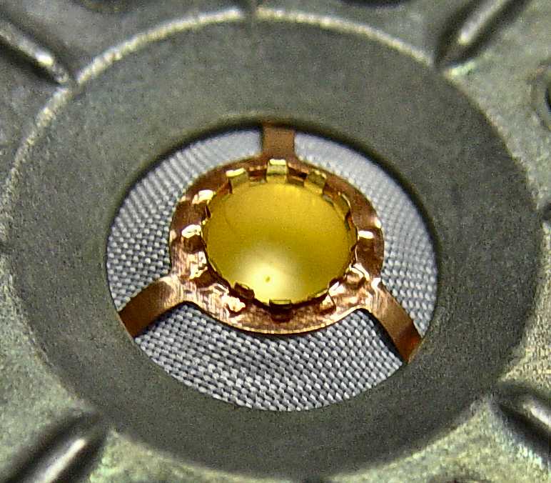
Close-up of gold “button cup” attached to center of aluminum diaphragm
Diaphragm remove from gold “button cup” exposing rest of structure under diaphragm
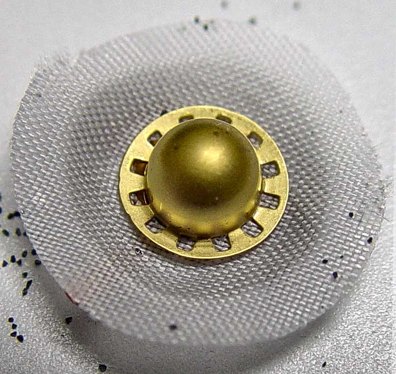
Close-up of gold “button cup” suspended by fabric material and conductive copper “ribbons”
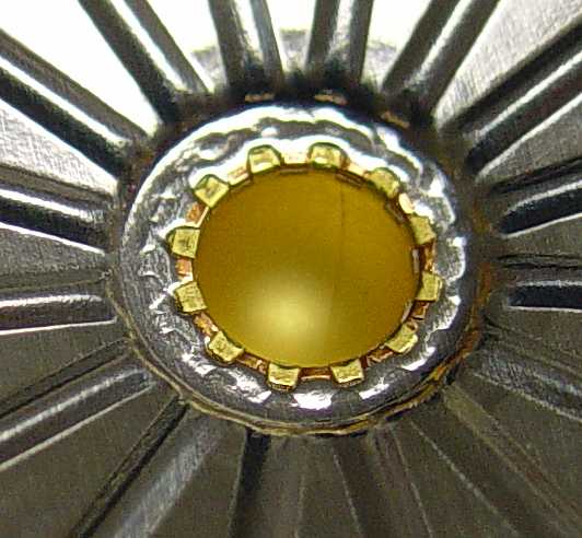
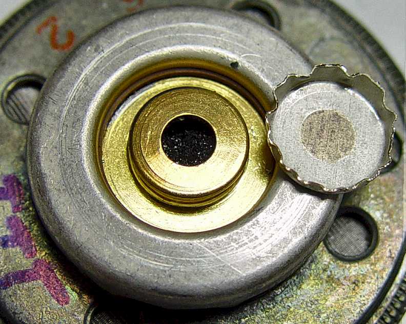
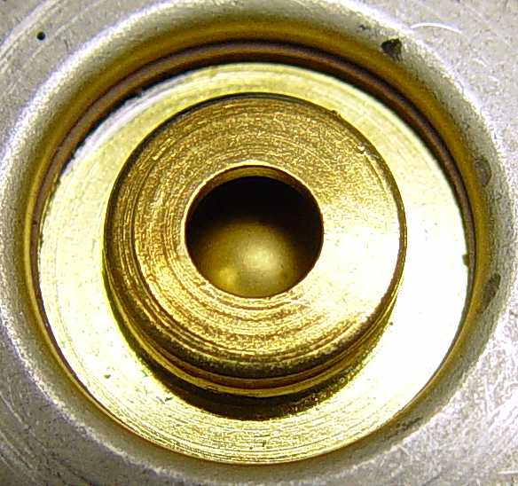
Rear button cup removed to expose opening in rear carbon granule chamber full of carbon granules
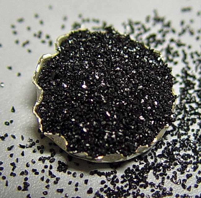
I poured out the carbon granules into the rear button cup for this photo
Gold “button cup” can be seen through hole in rear carbon chamber after carbon granules were removed
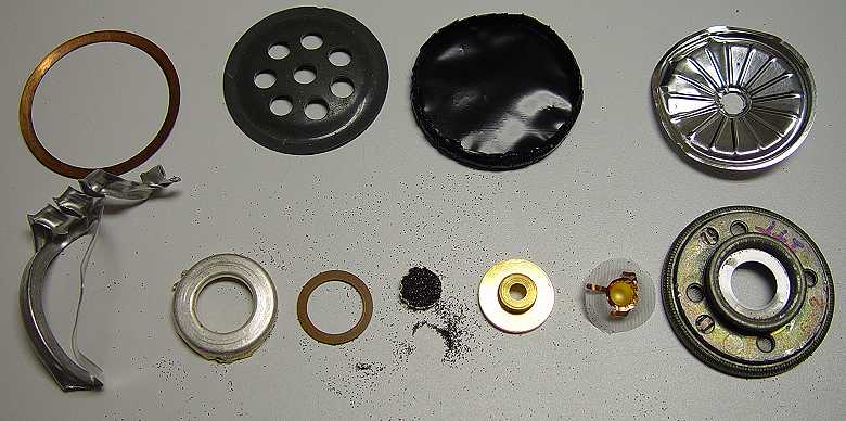
All the parts displayed that I took apart


Reliable, secure high-speed internet
With CenturyLink Simply Unlimited Internet, you can choose from a wide range of available speeds that fit your online needs. Plus, you can connect several devices with super-fast in-home WiFi.
Order Now