

Western Electric Products- Payphones and Phone Booths Modern Payphones
A look inside of a modern 1D2 model Western Electric payphone
Sewing Machine - Automatic Answering Service “Mirrophone” wire ribbon recorder/player Telephones - PicturePhone - Bell Chime
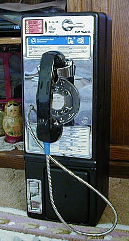
Western Electric (Bell System) single-slot rotary model made around 1978

We Offer Personalized One-On-One Service!
Call Us Today at (651) 787-DIAL (3425)

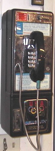
Western Electric (Bell System) single-slot Touch-Tone model (date unknown)
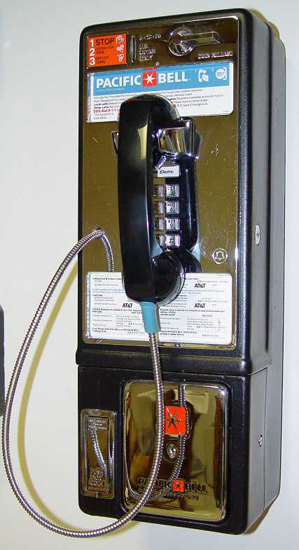
I purchased a Bell System/Western Electric touch-tone single-slot payphone (model 1D2) in really nice condition from a fellow club member and have taken several photos of the inside components and sub-assemblies for this web page. Before we look at the photos, let’s look at the assembly drawings and parts list for this phone. The file is large so if you have only a standard dial-up modem you will have to wait a while for it to download. To view/download the file, click HERE. Okay, now to the photos . . .
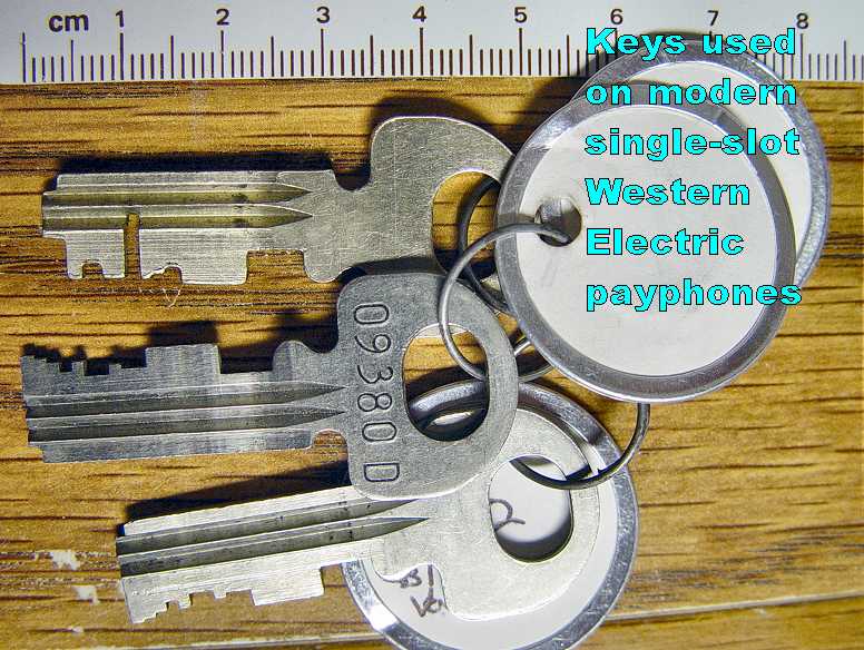
First, let’s take a look at the outside of the pay phone so you can familiarize yourself with the model I have. By the way, If you didn’t get keys and a “T” bar for your payphone then you are out of luck getting it open without damaging the case and other parts by using “brute force” like crowbars or dynamite! Locksmiths do not have and can not make keys for your payphone.
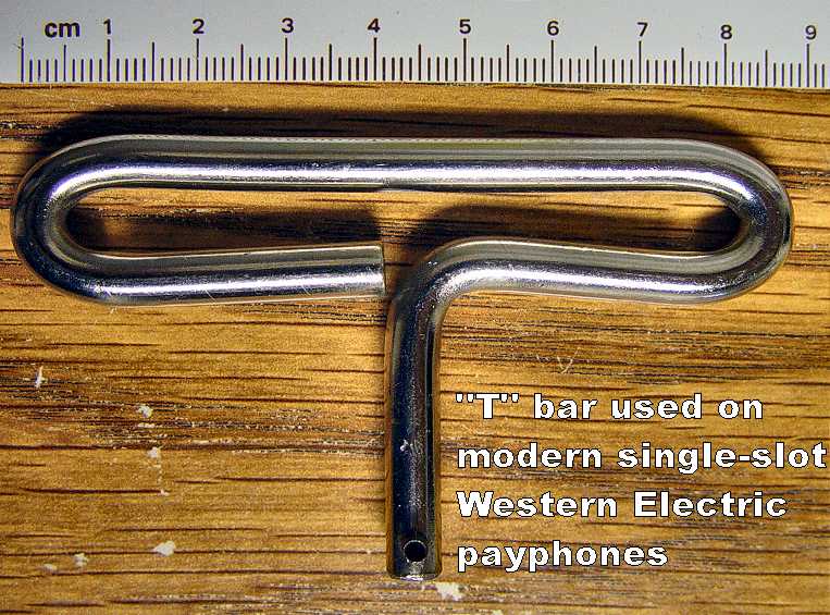
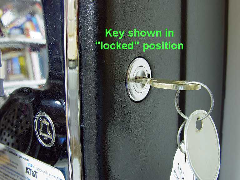
Now lets open the pay phone and see what’s inside. The “T” bar is used to secure phone once the key is locked.
Insert the key as shown here.
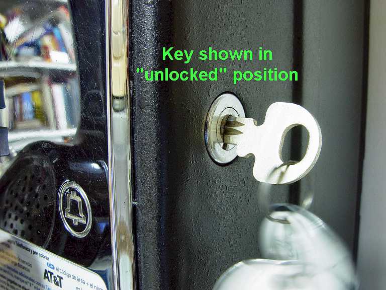
Rotate key clockwise about 90 degrees to the unlocked
position. Insert the “T” bar as shown here.
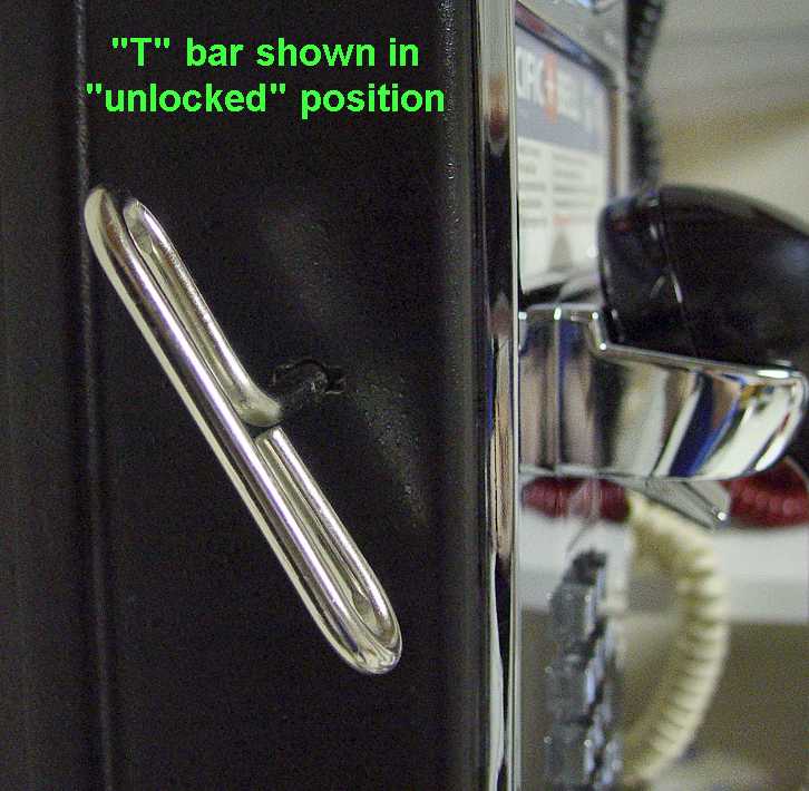
Rotate “T” bar counter-clockwise about 30 degrees to the unlocked
position.
CAUTION!
Okay, now that you’ve got your phone unlocked, be VERY CAREFUL when removing the front housing. THE FRONT HOUSING IS HEAVIER THAT IT LOOKS!
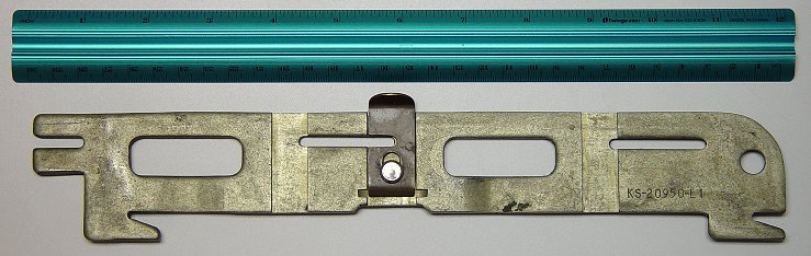
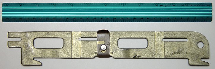
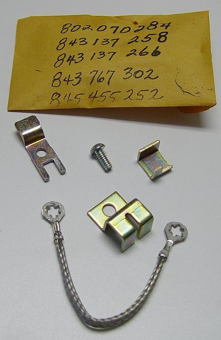
One thing you probably don’t have that you will see in my photos is a special “hanger bracket” to hang and hold the front housing open about 90 degrees from the rear housing. What does a hanger bracket look like? Here is mine shown with ruler in unlatched
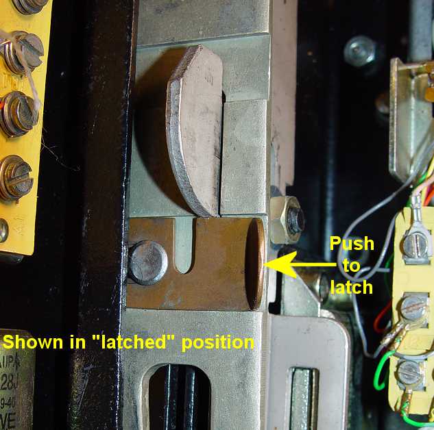
condition and latched
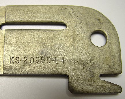
condition( close-up of latched condition as installed in phone). The Bell
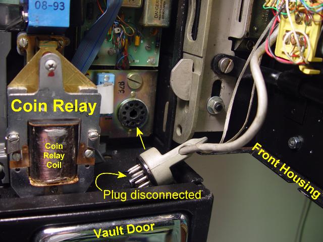
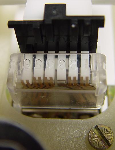
System Part Number is stamped into bracket. If you don’t have this special Bell System tool, you will need to unplug the front/rear housing interconnecting cable as shown** **here and carefully lay the front housing on a soft sturdy surface that won’t scratch the chrome or painted surfaces and can withstand the weight.
Now that we have the phone open, lets see what’s inside . . .
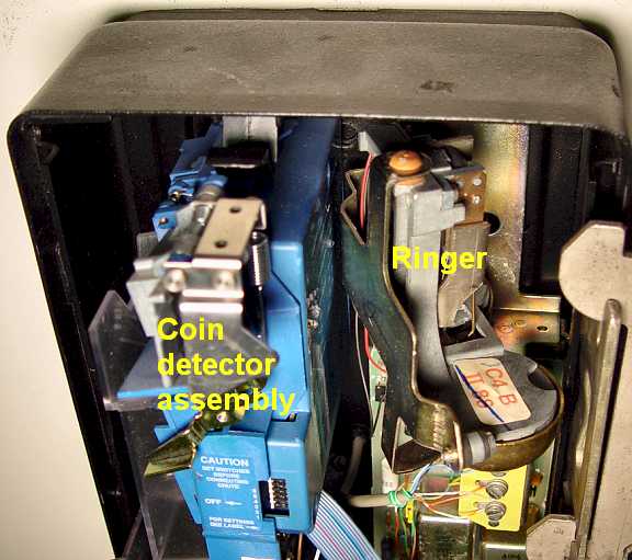
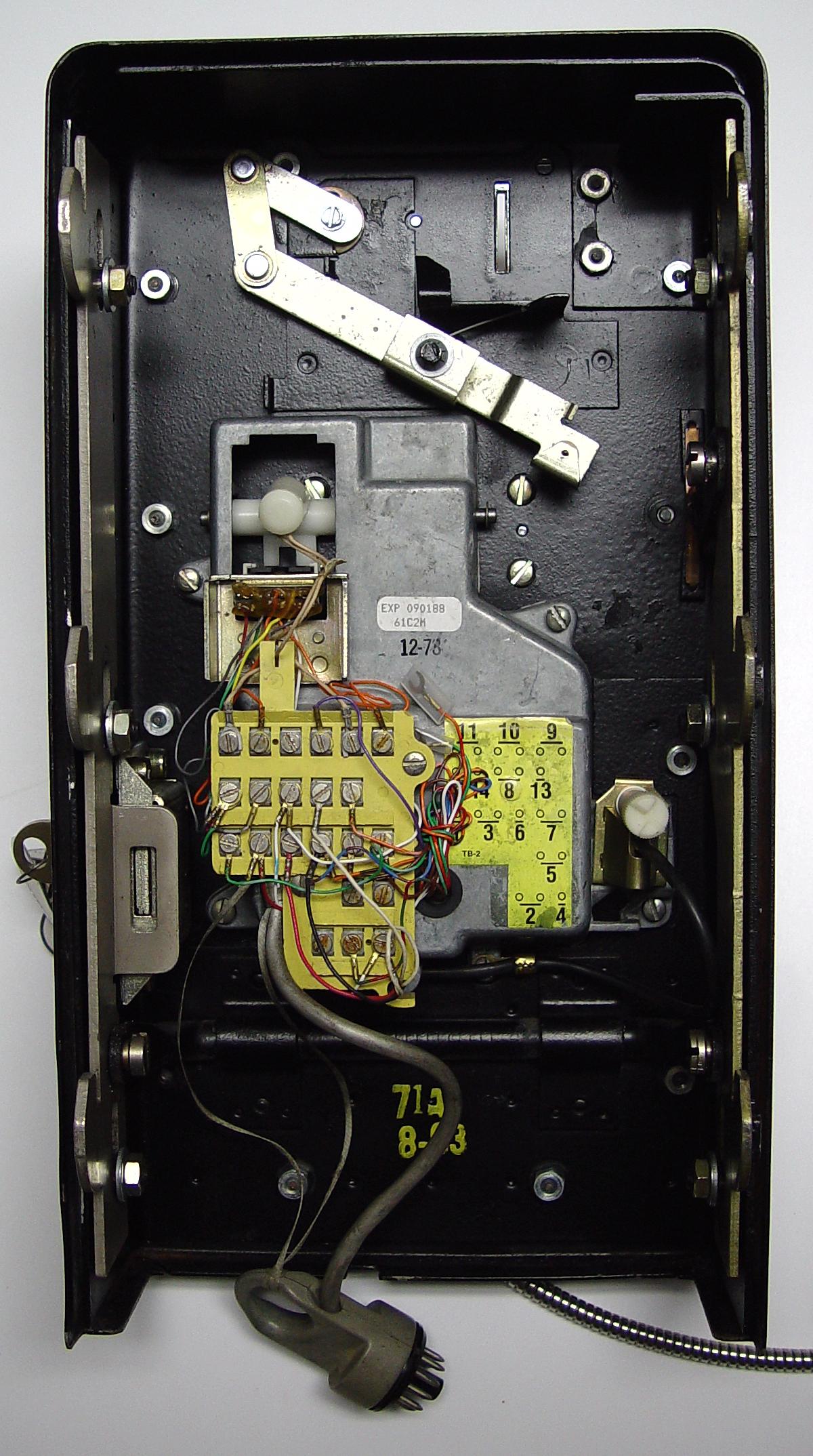
Rear Chassis Assembly
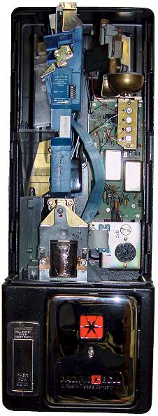
Overview of rear chassis assembly
Click here to view full-size
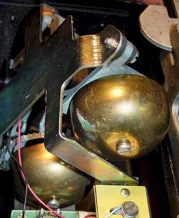
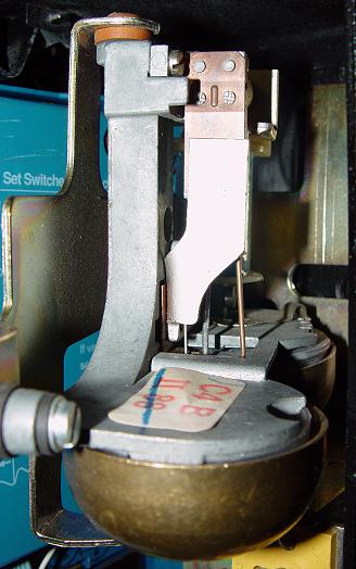
Bell ringer
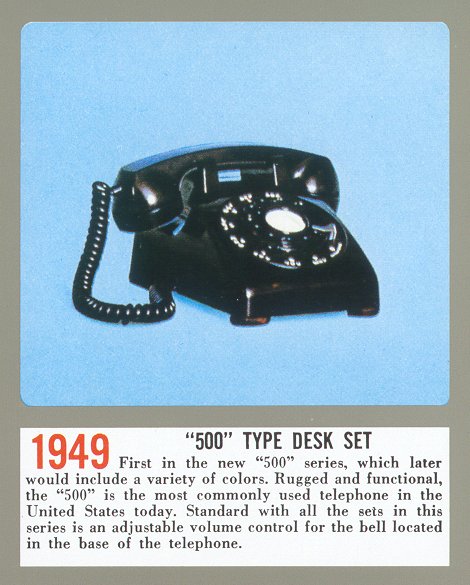
The bell** **ringer used in this payphone is the same as the one used in the famous Western Electric 500 model series, 554 model series, and 2500
model series along with several other model of telephone equipment. It is mounted at an angle in the upper right corner of the back housing as shown HERE (more photos are here and here.)
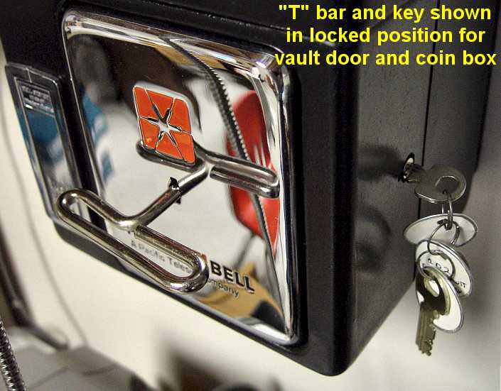
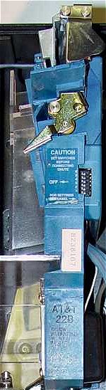
Coin Box and Vault Door
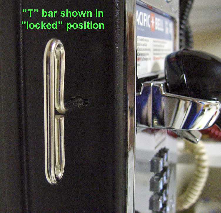
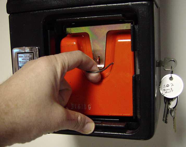
The coin box is protected from vandals by the “vault door”. You must use the “T”
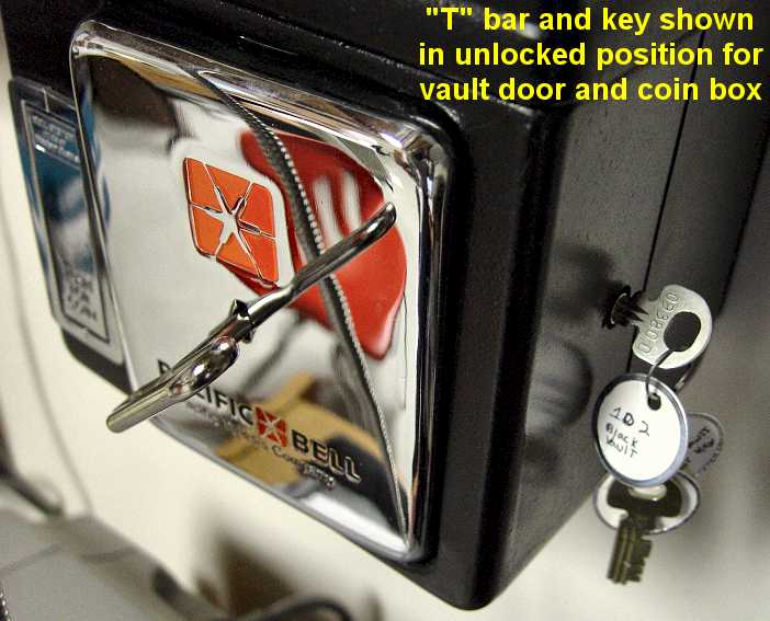
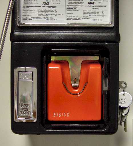
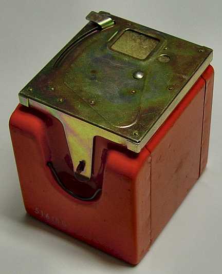
bar and have a special key (different from the upper housing key) to open the vault door to access the coin box.The position of the “T” bar and key when the vault door is locked is shown HERE. To unlock the vault door, first rotate the key clockwise about 135 degrees then, while holding the vault door in one hand to keep it from falling, turn the “T” bar counterclockwise about 45 degrees as shown HERE. Carefully remove the vault door (leaving “T” bar in place) and set it down on a soft, non-abrasive surface. Note, the vault door is heavier than it may look so be careful you don’t drop it on your toes! Here is a photo of the vault door removed exposing the coin box inside.
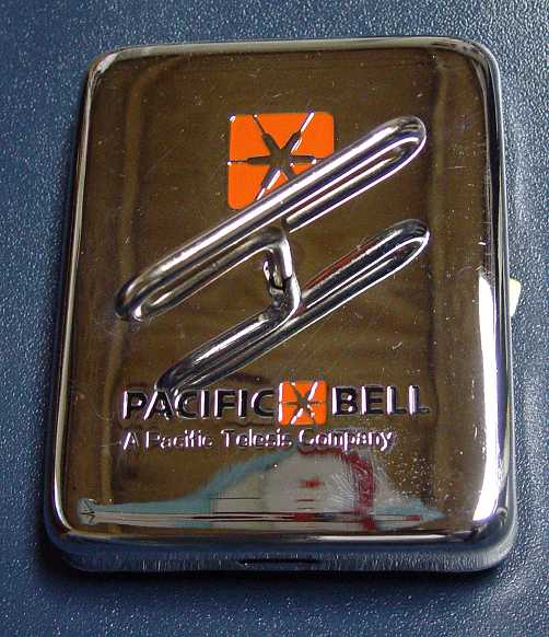
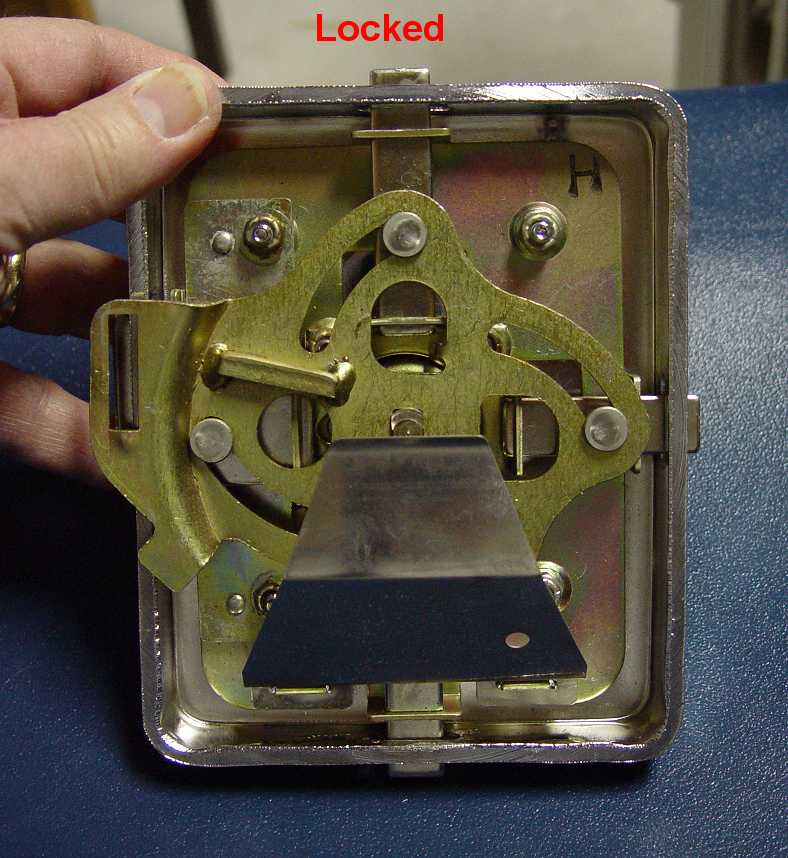
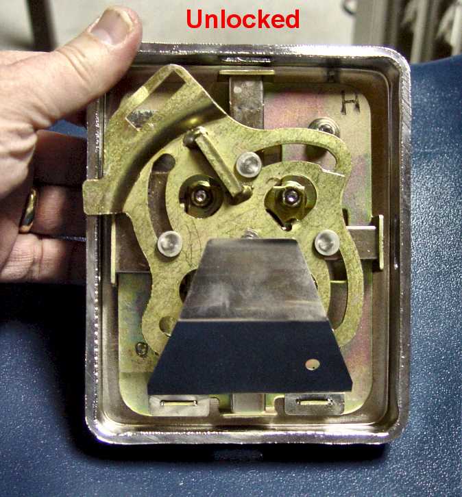
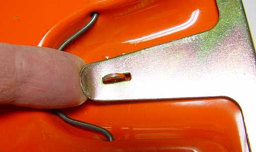
The vault door has an interesting mechanical locking mechanism as see in the following photos:
Locking mechanism shown in locked position
Locking mechanism shown in unlocked position
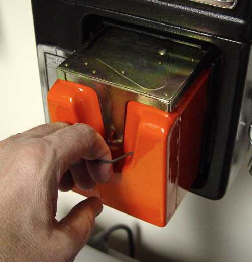
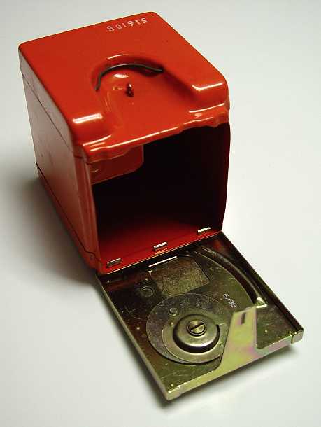
Next, lets remove the coin box. To do this, simply lift up and pull the wire pull-loop on front of coin box to slide coin box out of phone. To open the lid on the coin box, place finger under the lid’s “tongue” latch as shown HERE. Lift tongue latch up to release lid. The open coin box looks like this.
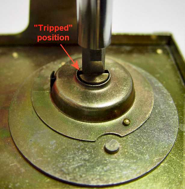
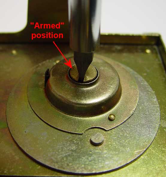
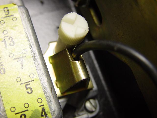
Now comes an important task you MUST do in order to get that coin box back into the payphone! When you removed the coin box from the pay phone, you ’tripped" a mechanism that prevents you from pushing the coin box back in the phone. You must “arm” the mechanism once it has been tripped. This is done with a simple flat-blade screw driver. Before explaining this, view the following two photos:
You must rotate that screw just over 90 degrees clockwise to “arm” your coin box so it can be put back into the phone.
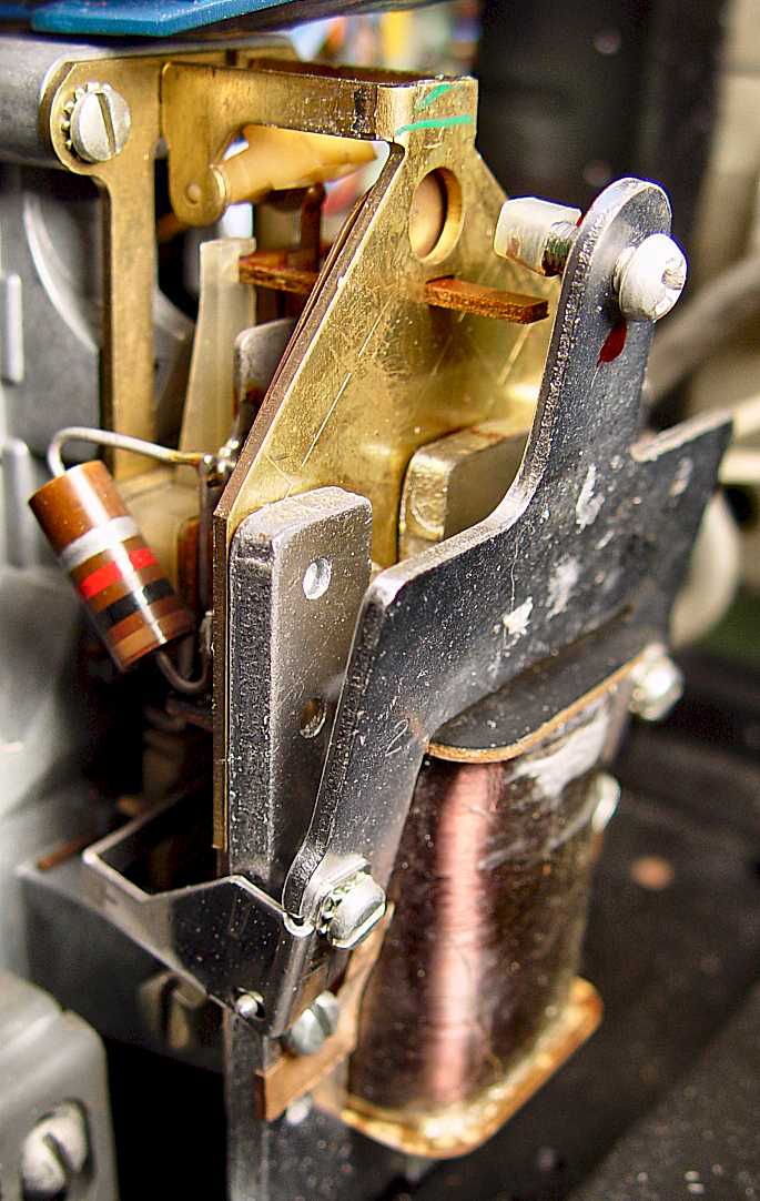
Coin Relay
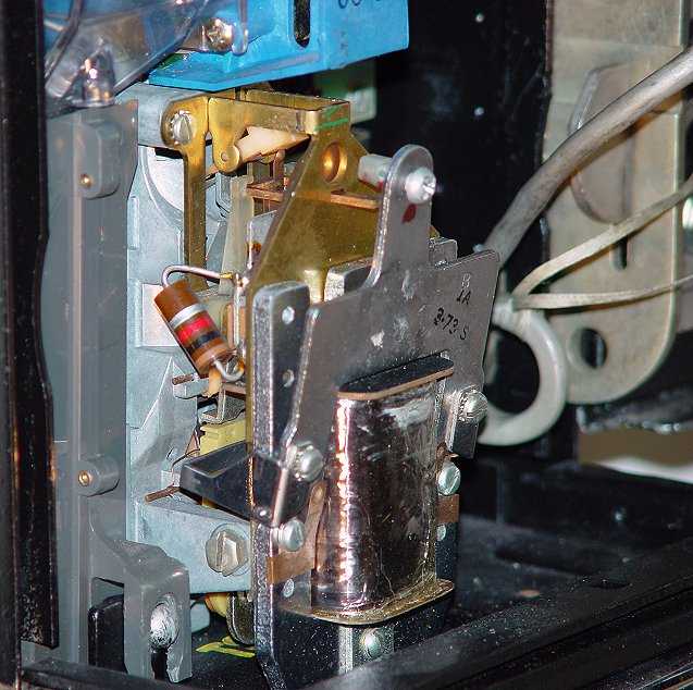
The coin relay is the device in the pay phone that determines if your coin deposit(s) are returned to you via the coin return (line busy, no answer, etc.) or if the coin(s) are sent to the coin box (completed call). The coin relay is sometimes missing from payphones people buy from the general public like on eBay because some people (unfortunately) remove them thinking that is the only way to “convert” the phones to non-coin use on regular home phone lines. Thus, this assembly is hard to come by if yours is missing since the relays are usually thrown away leaving more payphones than coin relays in the world. Some pay phone resellers also remove the coin relay unfortunately.
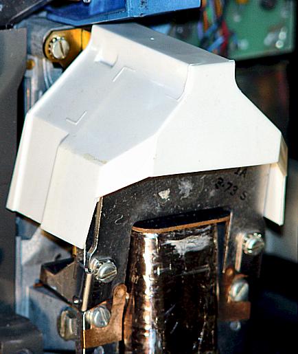
The coin relay has a white “plastic hat”. The plastic “hat” protects the relay contacts on top of the coin relay from being shorted out or damaged from stray coins that might fall down on top of the relay instead of traveling down the coin chute.
The coin relay consists of a coil, resistor, some electrical contacts (leaf-switch), armature and other parts.
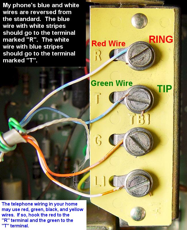
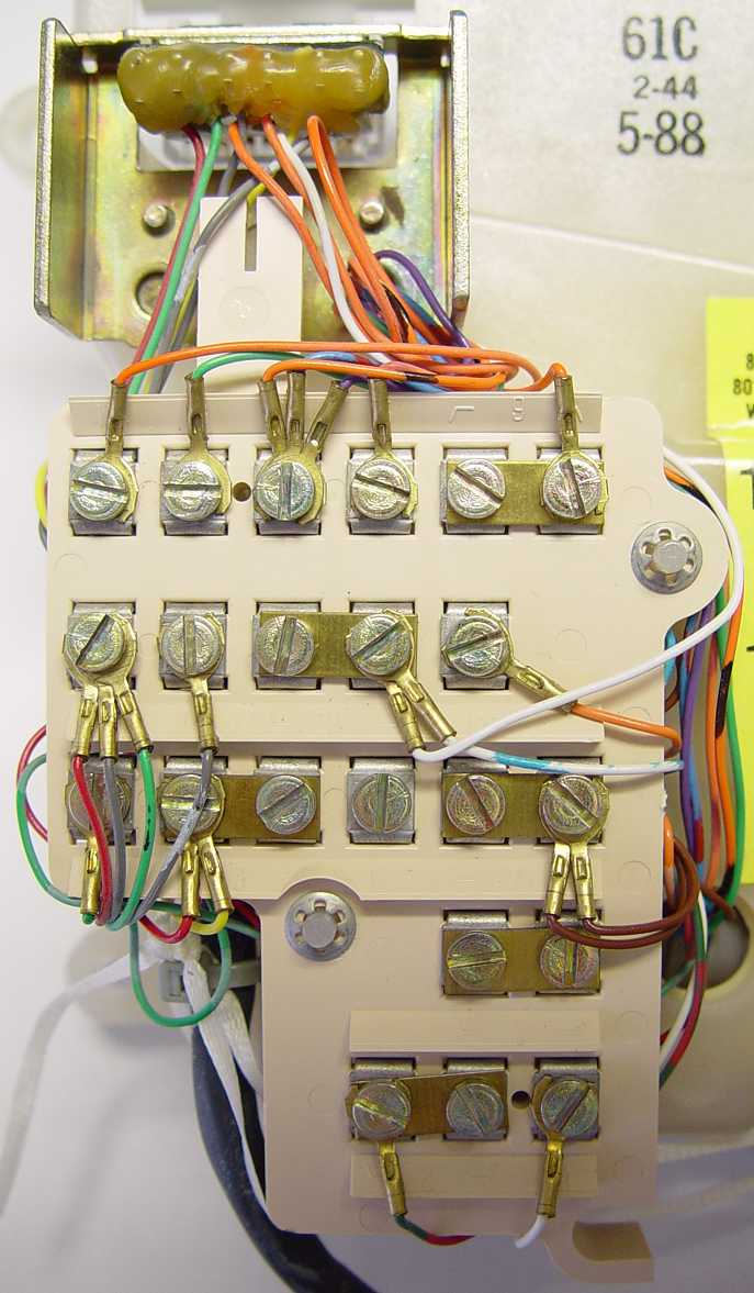
Terminal Strip
The telephone line wires are attached to the pay phone here. The “tip” and “ring” terminal screws are the two that you wire your phone line to. The polarity of the wiring to these screws usually don’t matter unless there is no built-in polarity guard on the touch-tone models of this phone. The lower two screws are for coin relay control voltages. More on that in a future update.
Front Chassis Assembly
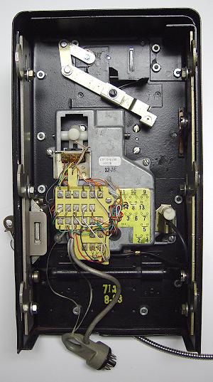
Overview of front chassis assembly
Click here to view full-size
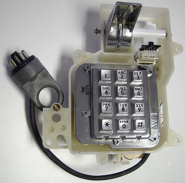
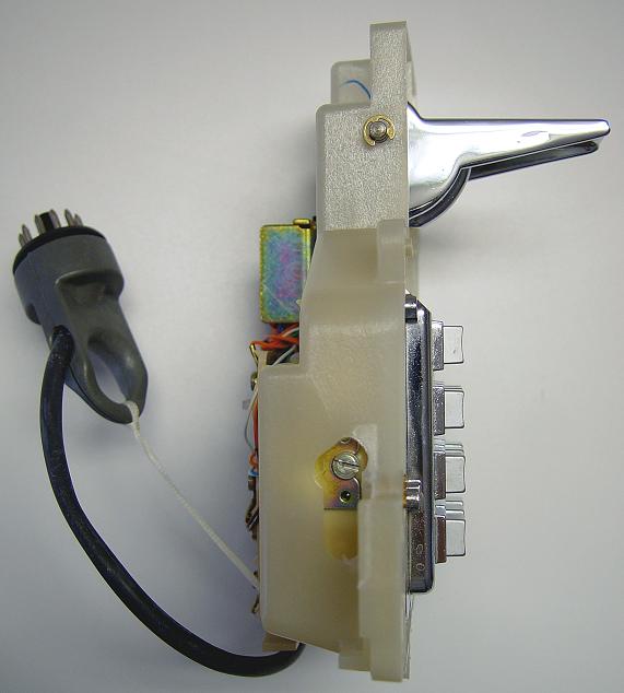
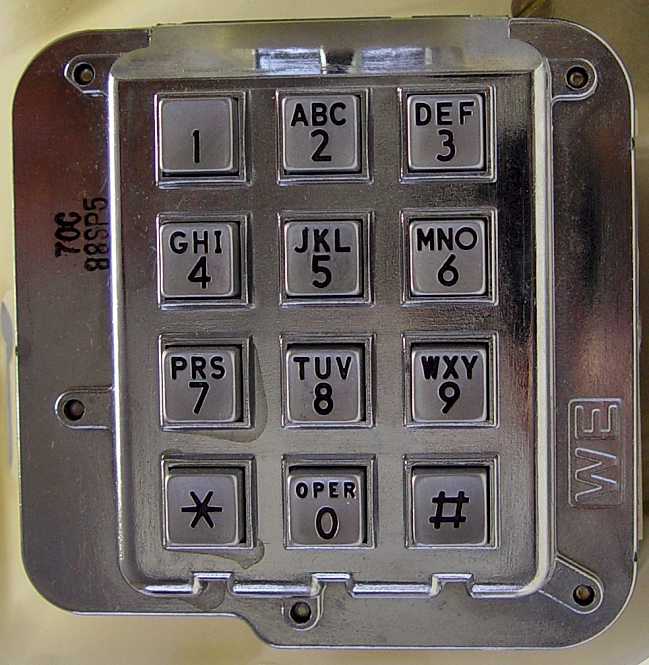
Touch-Tone Dial and Hook-Switch Assembly
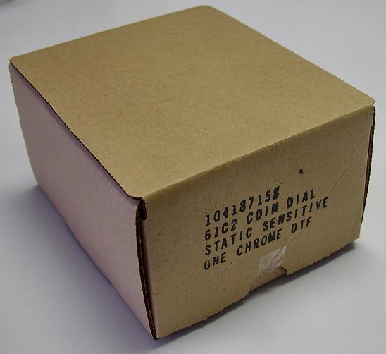
I was fortunate to find a new-in-box replacement touch-tone dial and hook-switch assemble for my phone on eBay. This will be a spare in case I ever have trouble with that assembly in my phone. It also served as a model for some photos I took for this web page.
For general view of this assembly, click HERE. To download the instruction sheets that came with my new assembly click HERE. The file is rather large so will take some time to download if you don’t have DSL or cable.
More photos:
Cord Clamp
This holds and secures the handset cord. Click here for photo.
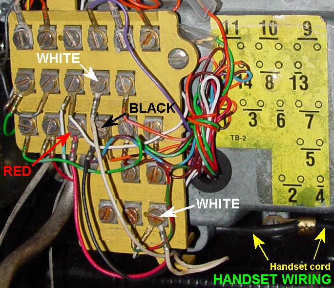
Handset Cord Wiring
So you have to replace your handset but can’t remember where the wires from the old handset cord went? Well, I’ve got just the photo to help you (assuming your handset has two white wires, a red wire and a black wire). Click HERE for photo.


Reliable, secure high-speed internet
With CenturyLink Simply Unlimited Internet, you can choose from a wide range of available speeds that fit your online needs. Plus, you can connect several devices with super-fast in-home WiFi.
Order Now