

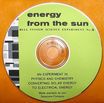
Energy From The Sun
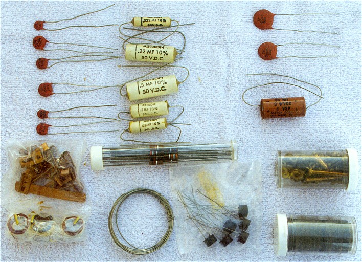 Photo 1
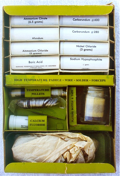 Photo 2
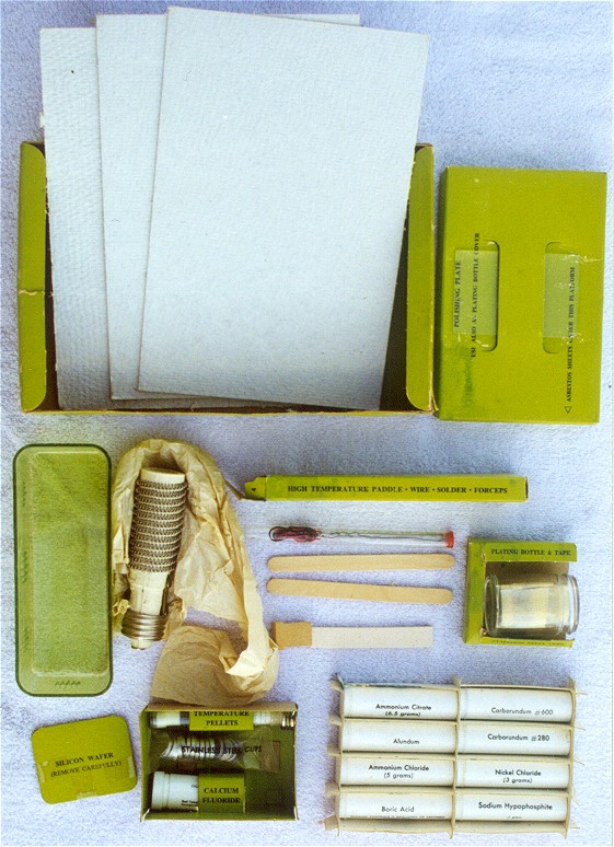 Photo 3
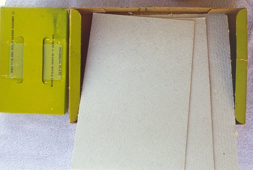 Photo 4
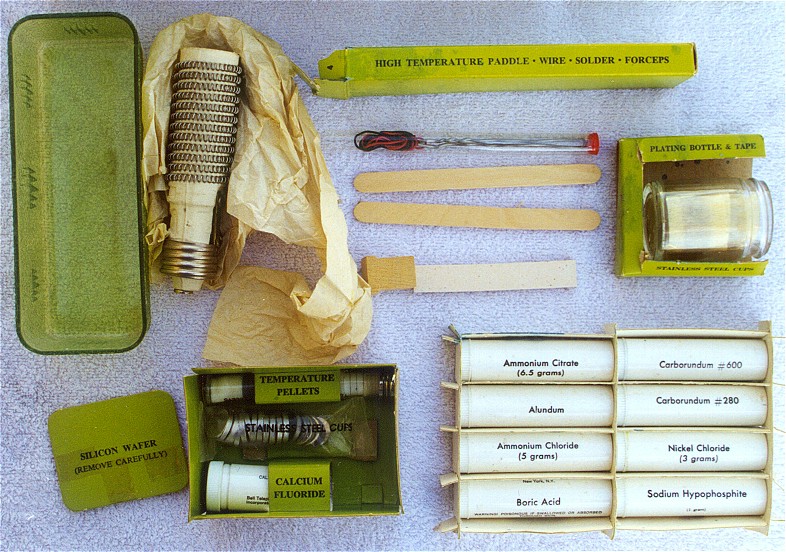 Photo 5
Note the three white “sheets” of asbestos in the top half of the picture above. At the time these kits were produced, the hazards of asbestos weren’t known.
Photo 1 shows kit with outer sleeve removed. Photo 2 shows the arrangement of the box contents. Photo 3 shows an overall view of the actual contents of the kit. Photo 4 show a close up of the three asbestos sheets and the polishing plate. Photo 5 shows a close up of the remaining parts. Note the heater element and just to the left of it is a plastic tray. The heater element was not included in some of the kits I’ve run across. There was a piece of paper with a notice about ordering the heater in the kits not having the heater. It is still being made today and is available for purchase from Cooper Wiring.
Make your own solar cell from raw materials! That is what you can do if you have this kit. This kit is not for the technically or dexterity challenged as you will be working with several toxic chemicals, asbestos, red-hot heating element and a very fragile thin raw wafer of silicon. For more information on photovoltaics (a.k.a., “solar battery”, “solar cell”, “solar panel”), see my web page dedicated to this subject by clicking HERE.
Chemical vials are in the lower right corner of photo 5. A thin and fragile piece of silicon is protected (and hidden from view) by a piece of cardboard shown in the lower left corner of photo 5. As with most other thumbnail images on these web pages, clicking on one of the images above will display the full- size image.

We Offer Personalized One-On-One Service!
Call Us Today at (651) 787-DIAL (3425)

A website visitor in Sweden contacted us about this kit and told about his work on new photovoltaic technology at the Ångström Solar Center (ÅSC), the photovoltaics research team at Uppsala University.
Based on an experiment shown in the manual for this Bell Labs Science Kit, he built a solar powered motor using scrap solar cell pieces and send the photos of his little motor. His description and photos of the motor follows:
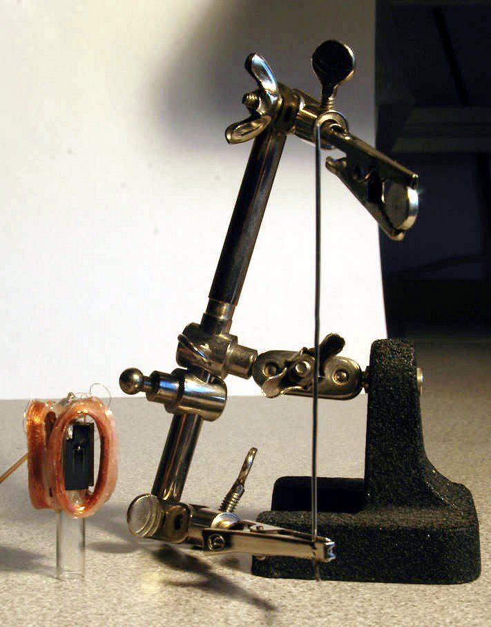
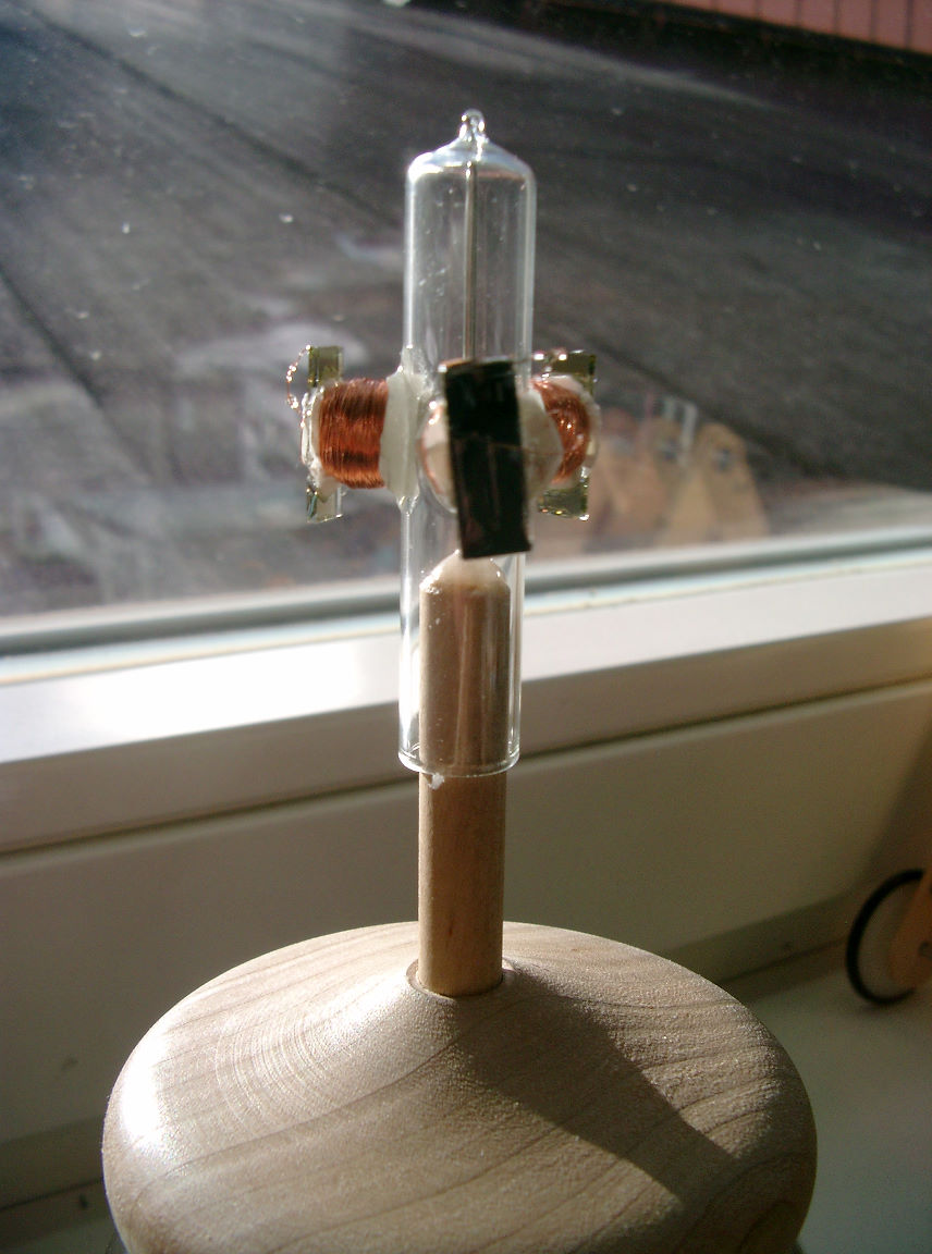
The rotor is about two inches high, the coils have a height of about one inch and are made up of 250 rounds of 0.1mm (AWG 38) enameled copper wire each. They measure about 30 ohms each, which is accidentally close to optimum performance with the .5 cm2 thin-film Cu(In,Ga)Se2 solar cell which is mounted in the center of each coil. These cells (they are poor, waste from our lab) give about 400mV at 8mA under full illumination (about 5% efficiency).
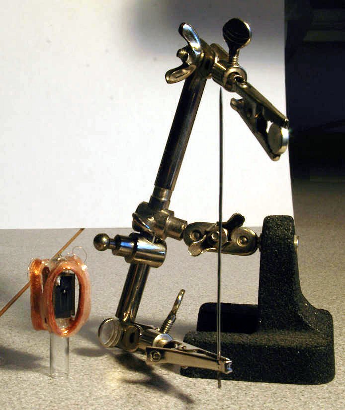
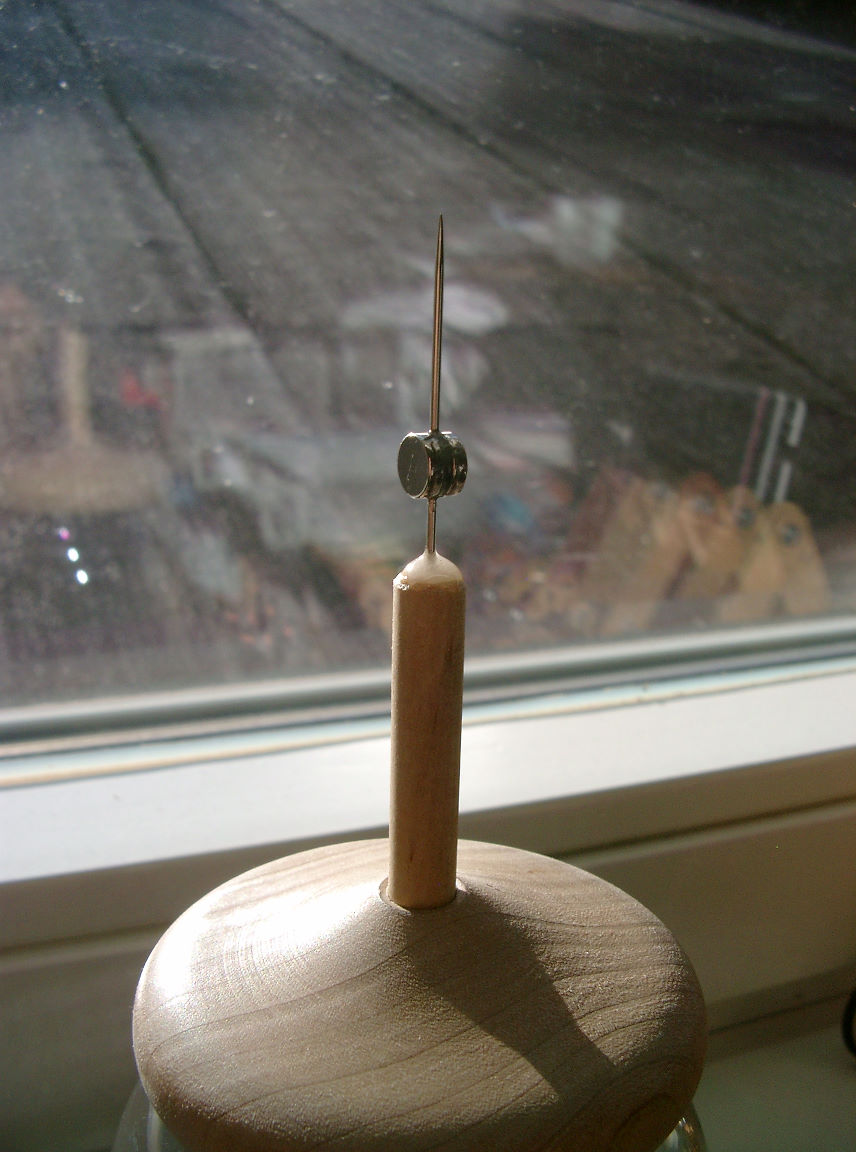
In the pictures the lamp is to the right and the small round thing in the upper alligator clamp is a neodymium permanent magnet. There is an angle of about 30 degrees between the incident light and the magnet, seen from the axis of rotation.
The body of the rotor is a 5mm diameter glass tube which I sealed on one side with a blow torch, forming a point. The coils and solar cells are glued onto the body with epoxy. After fixating the cells and coils, I soldered the thin wire onto the contact pads of the solar cells - each cell is only connected to its surrounding coil, all wound in the same direction.
The axis is an unwound, straightened safety pin - the longest needle I could find" - Uwe Zimmermann, PhD
Thin Film Solar Cell Group
Solid State Electronics
The Ångström Laboratory
Uppsala University
Box 534
SE-751 21 Uppsala, SWEDEN http://www.asc.angstrom.uu.se/tsc/tsc.htm
Here are the photos Uwe sent of his solar motor experiment. Click on images below to view full size.:
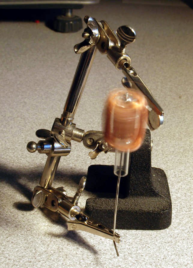
Motor spinning - 1
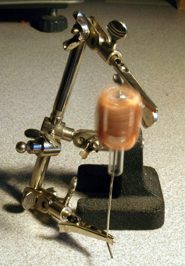
Motor spinning - 2
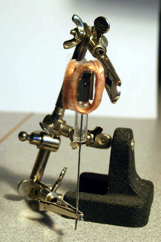
Motor stopped
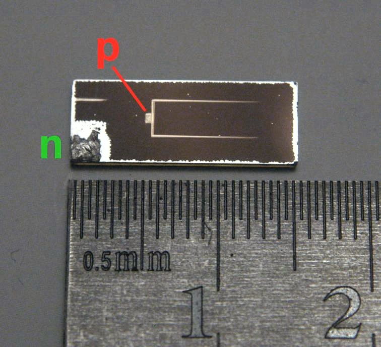
Close-up of solar cell
Motor components
separated - 1
Motor components
separated - 2
UWE’S SECOND SOLAR MOTOR
Mark 2
Uwe constructed a “new and improved” solar motor and sent me a video of it running in his window from the sunlight. He describes his second motor as follows:
“The main difference between the first design and “mark 2” is the use of paper bobbins for the coils and internally mounted permanent magnets on the needle - inside the rotor. The magnets are glued to the needle with epoxy resin, as are the coils ** **and solar cells to the glass tube itself.
The coils themselves are 500 turns of 0.1mm diameter (AWG 38) copper wire on a 5mm diameter paper bobbin. This gives about 30 ohms of resistance, which again is an almost optimum match to the used solar cells.
The rotor is a glass tube with about 10mm diameter and 5cm height. The top is drawn out to a point after heating the glass tube with a blow torch. It’s a bit off-center, hence the rotor tends to sway as it comes up in speed.”
CLICK HERE TO VIEW VIDEO OF MOTOR IN ACTION!
This kit came with a book of almost 100 pages of kit instructions, historical background on Solar Energy, the part that Bell Labs played in the commercialization of silicon solar cells and the physics of solar to electric conversion explained.
Sample pages from PDF File:


Reliable, secure high-speed internet
With CenturyLink Simply Unlimited Internet, you can choose from a wide range of available speeds that fit your online needs. Plus, you can connect several devices with super-fast in-home WiFi.
Order Now